Partitioned, Rotating Condenser Units to Enable Servicing of Submerged IT Equipment Positioned Beneath a Vapor Condenser Without Interrupting a Vaporization-Condensation Cycling of the Remaining Immersion Cooling System

a technology of immersion cooling and rotating condenser, which is applied in the direction of heat exchange equipment safety devices, lighting and heating equipment, instruments, etc., can solve the problems of large expansion space, communication latency, and significant workload of server, and achieve the effect of reducing the number of thermal challenges, and reducing the number of cooling units

Active Publication Date: 2014-08-07
DELL PROD LP
View PDF11 Cites 61 Cited by
  • Summary
  • Abstract
  • Description
  • Claims
  • Application Information

AI Technical Summary

Benefits of technology

[0010]According to one aspect, each individual condenser sub-unit includes a separate condensation surface from each other individual condenser sub-unit and a separate local conduit for providing condensation fluid to cool the separate condensation surface. During an opening of a first condenser sub-unit, each other individual condenser sub-unit that remains in a closed position continues to provide condensation of the rising vapor from the lower tank volume, while the first condenser sub-unit is open. Thus, an opening of the first condenser sub-unit does not hinder or prevent ongoing condensation from occurring at each adjacent second condenser sub-unit and the other non-adjacent condenser sub-units that remain in the closed position.

Problems solved by technology

These servers can perform significant workloads and generate and / or dissipate a large amount of heat during their operation.
As the need for access to greater and greater processing and storage resources continues to expand, limitations arise surrounding available space for expansion, building and equipment costs, and communication latency.
With the increasing processing and / or storage density in these rack-based server systems, the thermal challenges that result continue to be one of the biggest obstacles.
Conventional fan based cooling systems require large amounts of power, and the cost of power required to drive high flow fans increases exponentially with the increase in server densities.

Method used


Image

  • Partitioned, Rotating Condenser Units to Enable Servicing of Submerged IT Equipment Positioned Beneath a Vapor Condenser Without Interrupting a Vaporization-Condensation Cycling of the Remaining Immersion Cooling System
  • Partitioned, Rotating Condenser Units to Enable Servicing of Submerged IT Equipment Positioned Beneath a Vapor Condenser Without Interrupting a Vaporization-Condensation Cycling of the Remaining Immersion Cooling System
  • Partitioned, Rotating Condenser Units to Enable Servicing of Submerged IT Equipment Positioned Beneath a Vapor Condenser Without Interrupting a Vaporization-Condensation Cycling of the Remaining Immersion Cooling System

Examples


Embodiment Construction

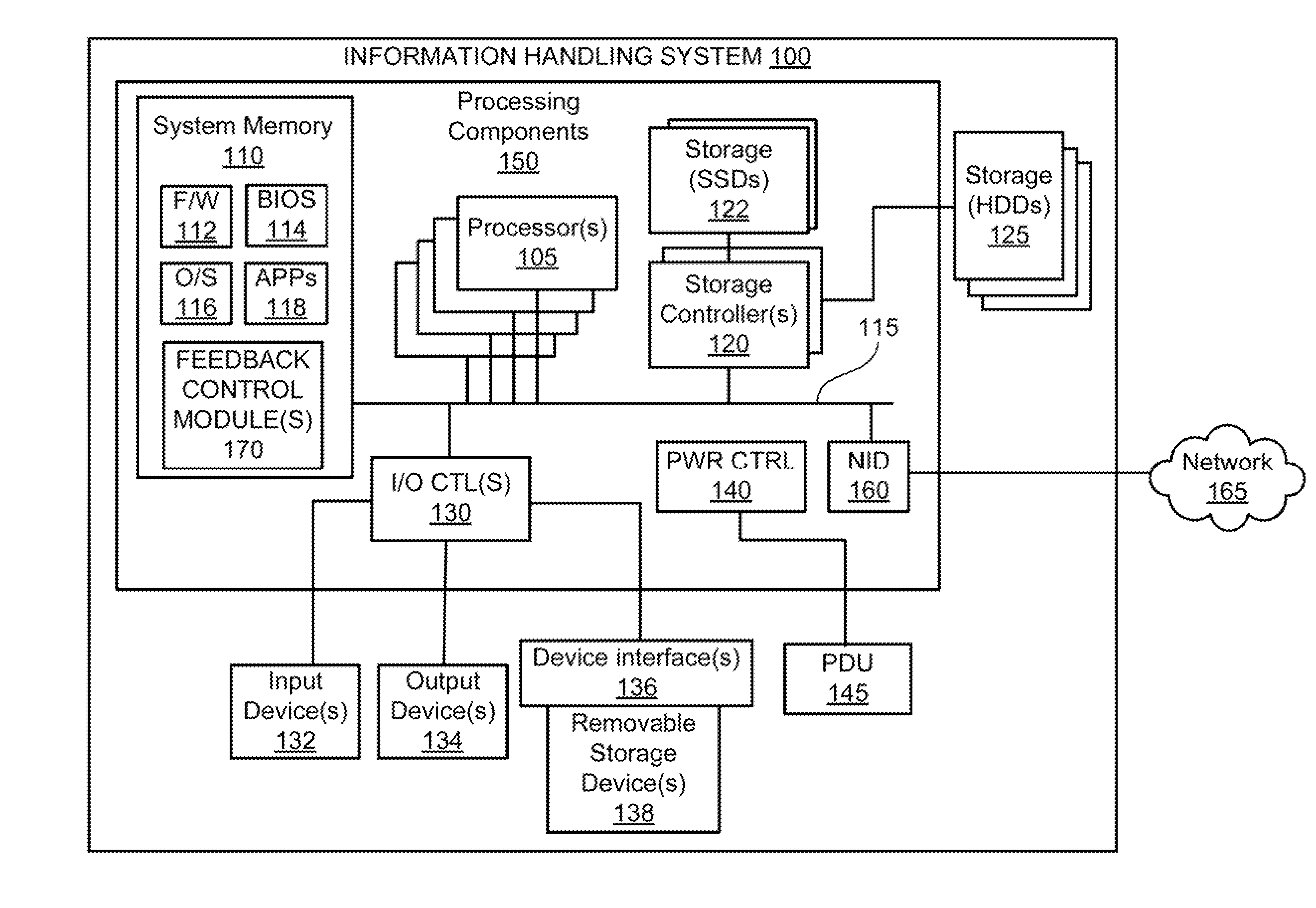
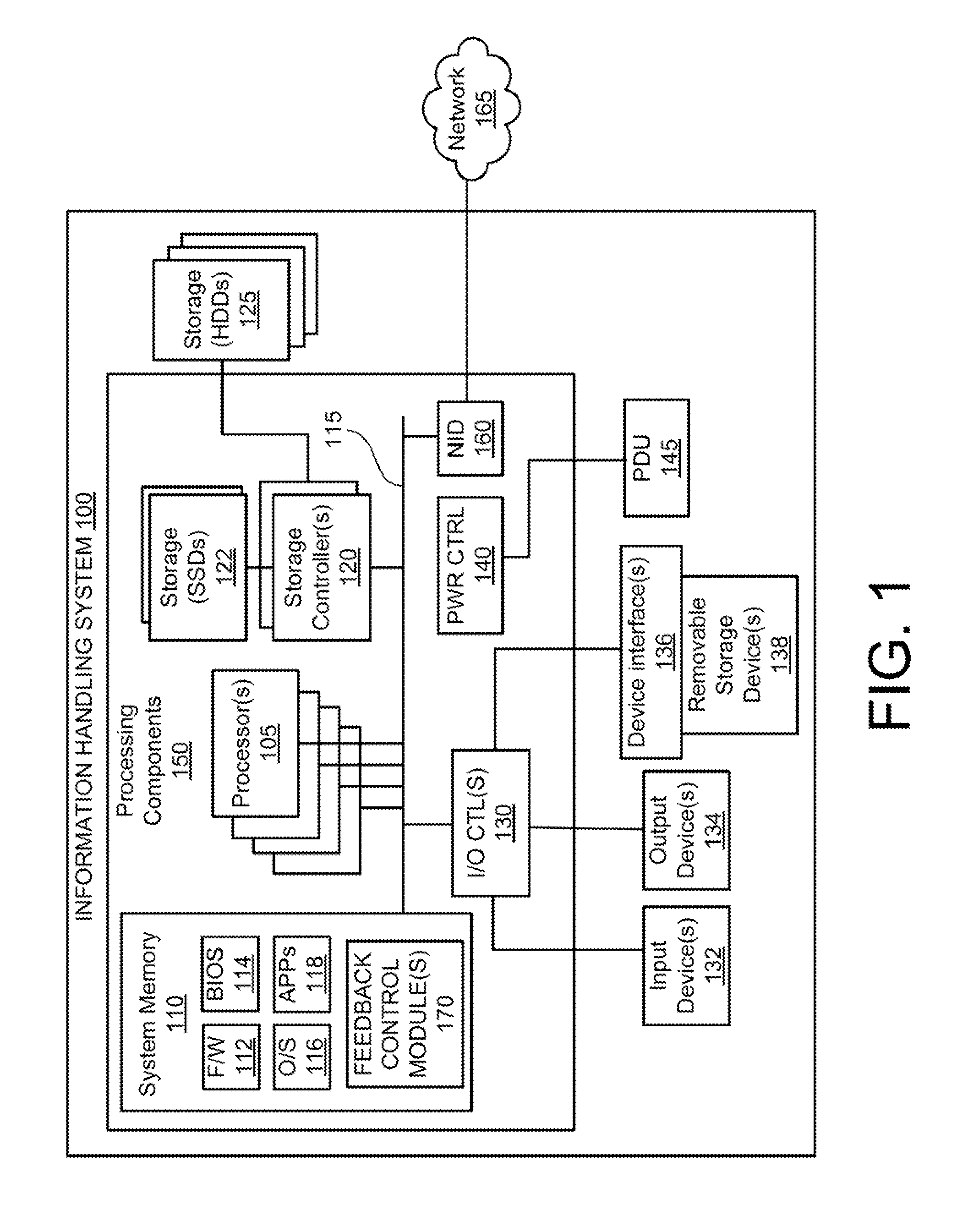
[0043]The present disclosure provides illustrative embodiments of various aspects of and / or different configurations and implementations of one or more systems, methods, and multi-phase heat transfer immersion cooling vessels that enable direct cooling of information handling systems, such as servers, by submerging at least a portion of the physical information handling systems in a dielectric liquid within a multi-phase heat transfer immersion cooling vessel.

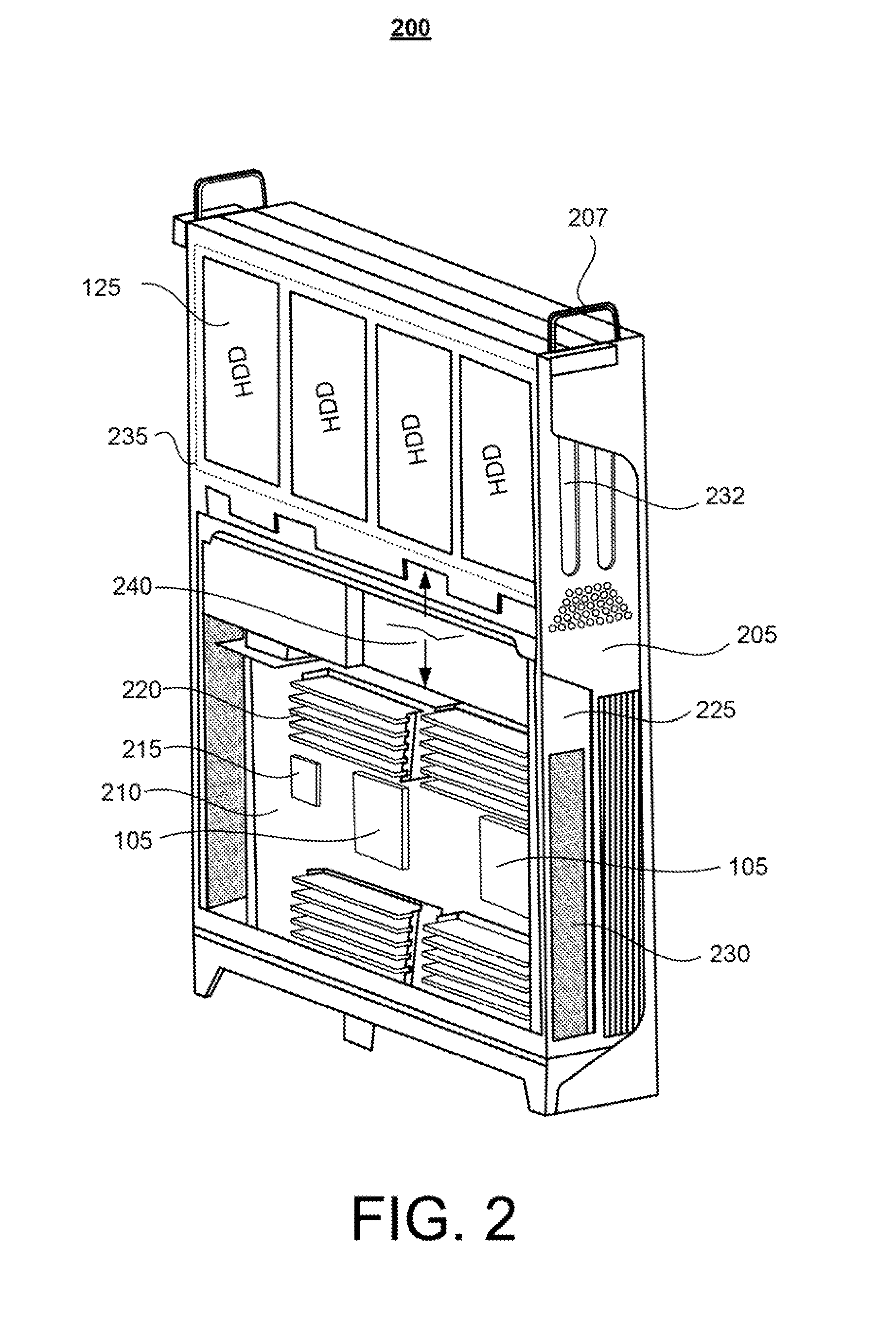
[0044]The disclosure generally includes a plurality of different aspects and multiple different embodiments, and each aspect along with the associated embodiments are described in detail below within one of the titled Sections A-K. A first aspect of the general disclosure, presented in Section A, provides examples of an information handling system and of two different servers configured and / or oriented for use within a rack-based immersion cooling system. Section B, which describes the second aspect of the general disclosure, i...


PUM


Abstract

An immersion cooling tank includes: a tank comprised of a base wall, and perimeter walls, and having a lower tank volume in which a liquid can be maintained and heated to a boiling point to generate a rising plume of vapor; a rack structure within the tank volume that supports insertion of multiple, heat dissipating electronic devices in a side-by-side vertical configuration; and a condenser configured as a plurality of individually rotatable condenser sub-units, with each condenser sub-unit located above a vertical space that extends vertically from the lower tank volume and within which an electronic device can be inserted. Each individual condenser sub-unit can be opened independent of the other sub-units and each other condenser sub-unit can remain in a closed position while a first condenser sub-unit is opened to allow access to a first vertical space and any existing electrical device contained therein below the first condenser sub-unit.

Description

BACKGROUND[0001]1. Technical Field[0002]The present disclosure generally relates to operating electronic devices within an immersion cooling vessel and in particular to a system and method for 2-phase liquid cooling of electronic devices within an immersion cooling vessel. Still more particularly, the present disclosure relates to a system and method for enabling direct access to electronic devices within an immersion cooling vessel without interrupting the cooling cycle of other electronic devices within the immersion cooling vessel.[0003]2. Description of the Related Art[0004]As the value and use of information continue to increase, individuals and businesses seek additional ways to process and store information. One option available to users is information handling systems. An information handling system generally processes, compiles, stores, and / or communicates information or data for business, personal, or other purposes thereby allowing users to take advantage of the value of ...

Claims


Application Information

Patent Timeline
Patent Type & Authority Applications(United States)
IPC IPC(8): F28F13/00
CPCF28F13/00F28F13/06F28B9/06F28D15/02F28D15/0266F28D15/06F28F2265/12F28F2280/105H05K7/20809H05K7/20827H05K7/20818H05K7/203G06F1/20H05K7/20781H05K7/20318F28D2015/0216
Inventor SHELNUTT, AUSTIN MICHAELCURLEE, JAMES D.MILLS, RICHARD STEVEN
Owner DELL PROD LP
Why Eureka
Try Eureka