
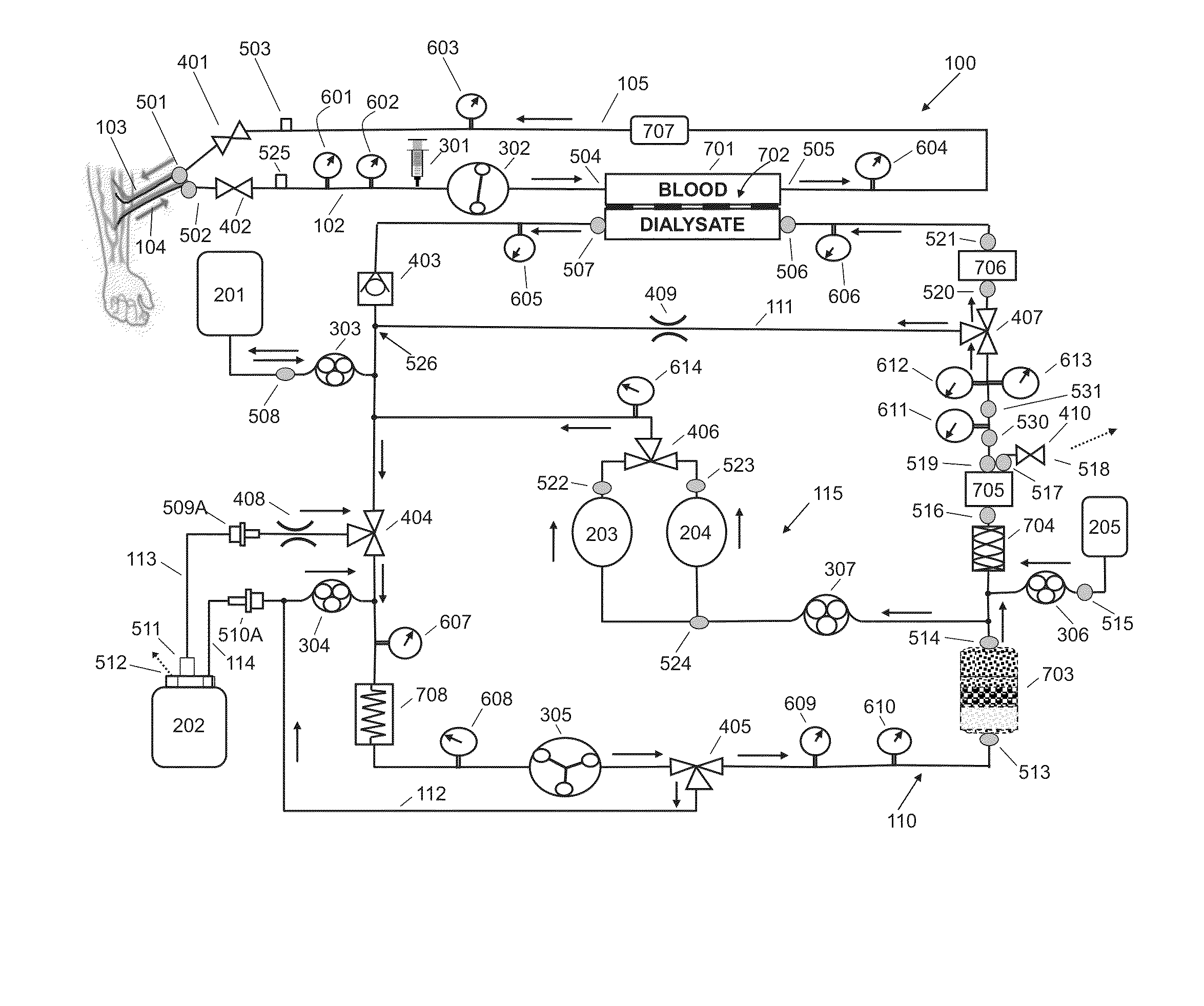
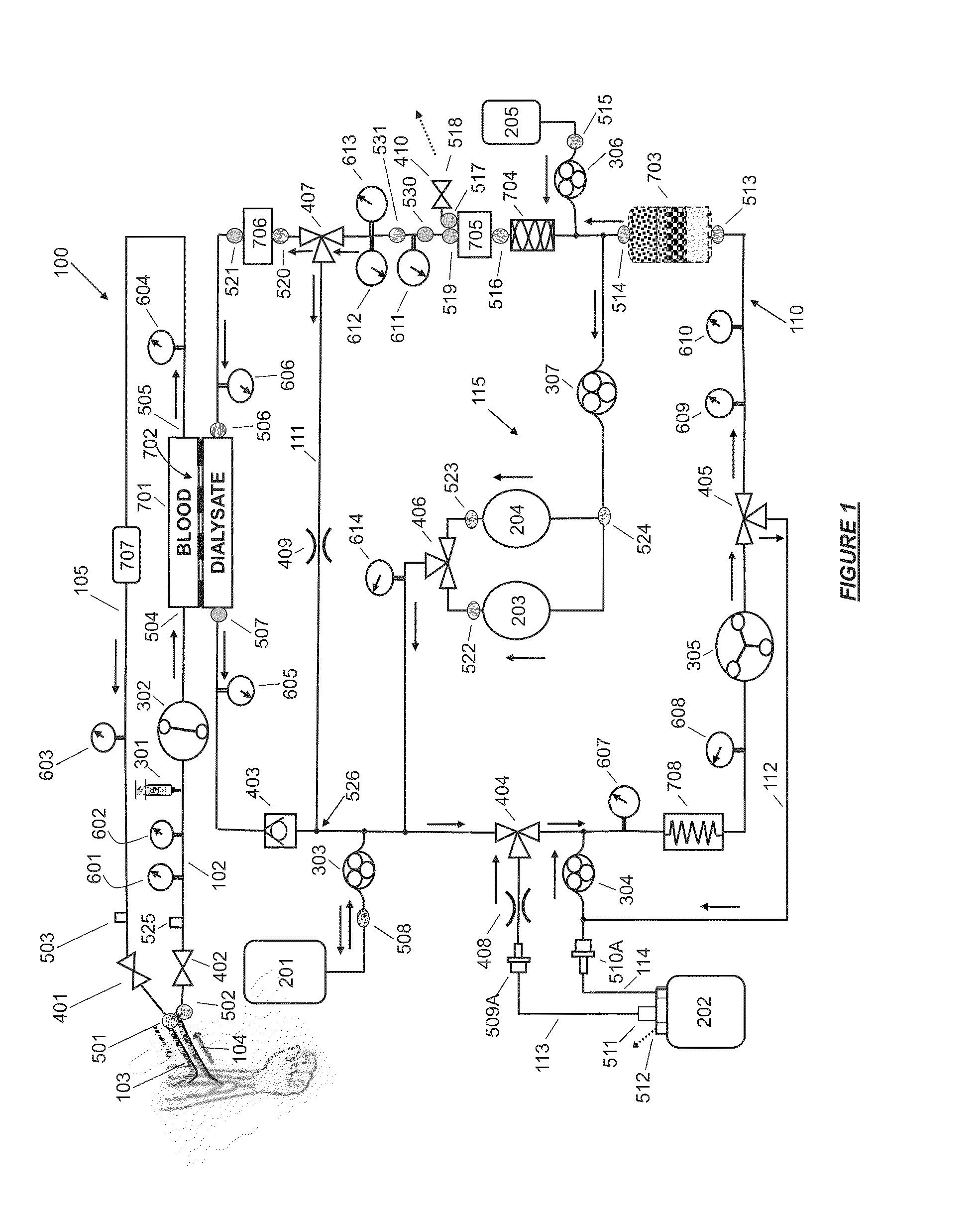
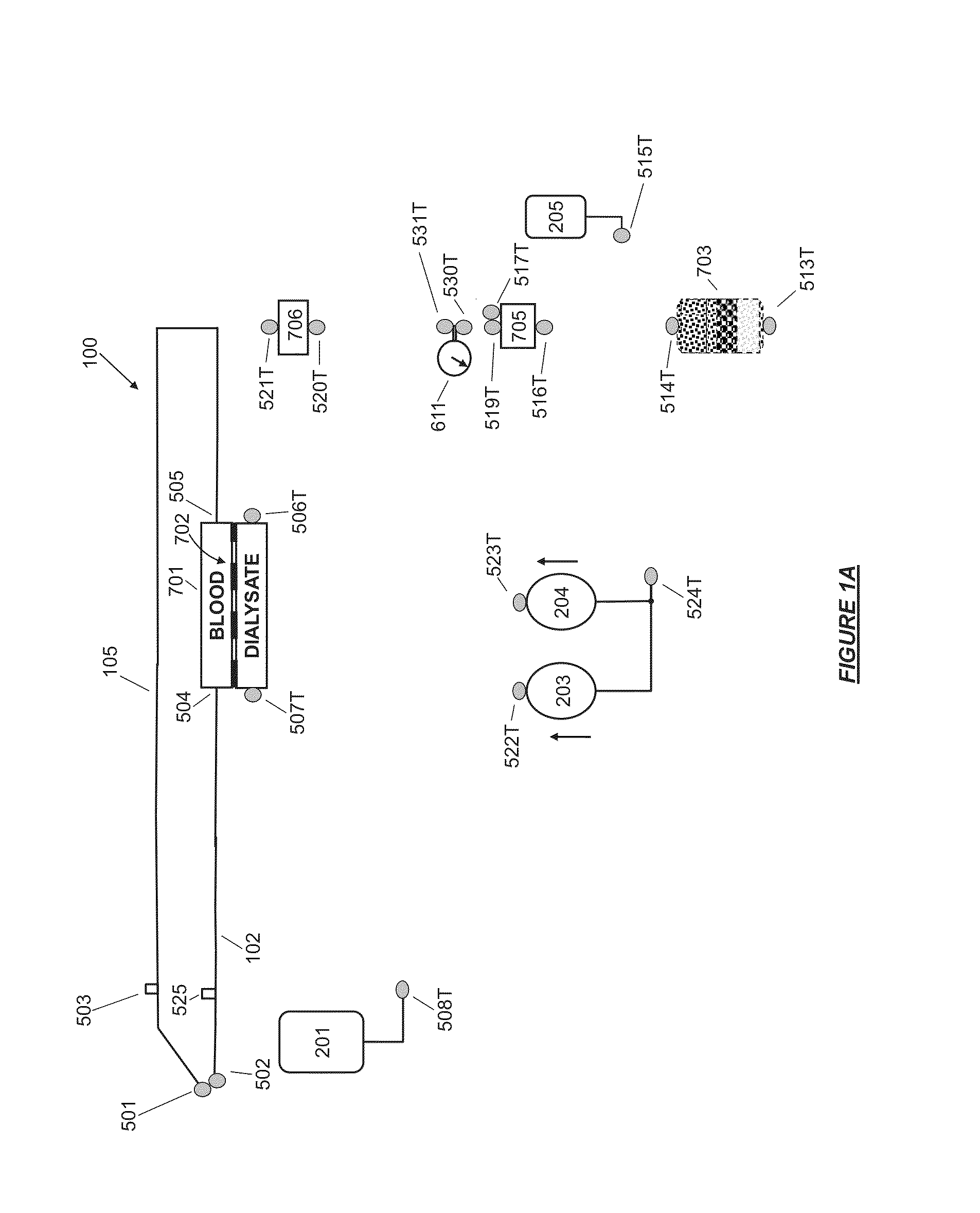
Fluid circuit for delivery of renal replacement therapies

a technology of fluid circuit and renal replacement therapy, which is applied in the direction of filtration separation, moving filter element filter, separation process, etc., can solve the problems of dialysis treatment, no cure, and inability to emulate the continuous function of a natural kidney

Active Publication Date: 2014-08-07
MOZARC MEDICAL US LLC
View PDF6 Cites 82 Cited by
  • Summary
  • Abstract
  • Description
  • Claims
  • Application Information

AI Technical Summary

Benefits of technology

The present invention describes a flow loop for hemodialysis and hemofiltration that has a controlled compliant flow path for preparing fluids required for the therapy session. The controlled compliant flow path can modify water into any one of a solution for priming a hemodialysis system, a physiologically compatible solution for contacting blood, a physiologically compatible solution for infusion to a subject, and a solution for blood rinse back to a subject. The flow loop can have a means for selectively metering in and out fluid from the controlled compliant flow path using a fluid balance control pump and a reservoir. The flow loop can also have a pump or valve in fluid communication with the controlled compliant flow path and a buffer source or sodium source, a pump in fluid communication with a conduit of the controlled compliant flow path and a reservoir, a first bypass conduit with a control valve, and a second microbial filter. The technical effects of the invention include improved efficiency and accuracy of fluid preparation for hemodialysis and hemofiltration therapy sessions.

Problems solved by technology

As the disease severity progresses, a patient with severe renal failure develops many symptoms that, if left untreated, eventually result in death.
Although the population of patients afflicted with CKD grows each year, there is no cure.
Although effective at removing wastes from blood, dialysis treatments are administered intermittently and therefore do not emulate the continuous function of a natural kidney.
Moreover, there are many inconveniences associated with dialysis, such as the necessity of traveling to a dialysis center and committing to time consuming treatments multiple times per week.
These variations result in patient complications and the high rates of patient morbidity and mortality.
Despite the clinical results from the Culleton and FHN research, few patients presently undergo a higher frequency of dialysis treatment.
More frequent hemodialysis is only used on a small part of the patient population due to the burden and cost of more frequent therapies.
Even the thrice weekly-regime is a significant burden to ESRD patients, and an increase in treatment frequency can often be difficult due to the deficiencies in known devices and the cost of the additional treatments.
The typical requirement for large amounts of purified water creates a barrier in that stationary, expensive, and often architecturally incompatible water purification supply and drain systems must be connected to the plumbing.
A different water-related barrier to treatment exists in some developing regions of the world, in that infrastructure to produce the large volumes of purified water may not exist within feasible traveling distance for persons suffering from ESRD.
However, existing technologies for regenerating spent dialysate have been met with various limitations.
Additionally, REDY systems have limited or no ability to remove sulfates, and may not be easily portable by the individual receiving therapy.
Yet one of the problems associated with sorbent regeneration of spent dialysate is the buildup of sodium ions released as a byproduct of the adsorption process, thus necessitating a high degree of sodium concentration control which has yet to be achieved by currently available wearable or portable dialysis systems.
However, the introduction of tap water into a dialysis system necessitates additional purification measures, thus adding to system complexity and size.
As a result, such systems may not be useful for mobile or portable use.

Method used


Image

  • Fluid circuit for delivery of renal replacement therapies
  • Fluid circuit for delivery of renal replacement therapies
  • Fluid circuit for delivery of renal replacement therapies

Examples


Embodiment Construction

Definitions

[0114]Unless defined otherwise, all technical and scientific terms used herein generally have the same meaning as commonly understood by one of ordinary skill in the relevant art. The definitions provided herein should not be rigidly construed without taking into account the context and other ascribed meanings provided, or by their use, in other parts of the specification, claims, and drawings.

[0115]The articles “a” and “an” are used herein to refer to one or to more than one (i.e., to at least one) of the grammatical object of the article. By way of example, “an element” means one element or more than one element.

[0116]An “acid” can be either an Arrhenius acid, a Brønsted-Lowry acid, or a Lewis acid. The Arrhenius acids are substances or fluids which increase the concentration of hydronium ions (H3O+) in solution. The Brønsted-Lowry acid is a substance which can act as a proton donor. Lewis acids are electron-pair acceptors

[0117]The term “cation infusate pump” historical...


PUM

PropertyMeasurementUnit
Temperatureaaaaaaaaaa
Electrical conductivityaaaaaaaaaa
Flow rateaaaaaaaaaa

Abstract

A flow loop for hemodialysis, hemodiafiltration and hemofiltration for the treatment of pathological conditions such as End Stage Renal Disease (ESRD) that has a controlled compliant flow path for preparing fluids required for a hemodialysis therapy session from water. The controlled compliant flow path modifies water into any one of a solution for priming a hemodialysis system, a physiologically compatible solution for contacting blood, a physiologically compatible solution for infusion to a subject, and a solution for blood rinse back to a subject. The controlled compliant flow path has a means for selectively metering in and metering out fluid from the flow path.

Description

FIELD OF THE INVENTION[0001]This disclosure relates to an apparatus for hemodialysis and hemofiltration for the treatment of pathological conditions such as End Stage Renal Disease (ESRD). The systems and methods can have a controlled compliant flow path for preparing all fluids required for a hemodialysis therapy session from water wherein the controlled compliant flow path modifies water into any one of a solution for priming a hemodialysis system, a physiologically compatible solution for contacting blood, a physiologically compatible solution for infusion to a subject, and a solution for blood rinse back to a subject. The systems can have a dialyzer, control components, dialysate regeneration cartridge and fluid reservoirs configured to be capable of operating free of infrastructure utilities required for a high volume of purified water source and sufficient drain. The systems and methods are configured to have a suitable weight and design to be carried by an individual includin...

Claims


Application Information

Patent Timeline
IPC IPC(8): A61M1/16
CPCA61M1/1656A61M1/3465A61M1/3646A61M1/3649A61M1/3644A61M1/1658A61M1/1664A61M1/1668A61M1/3606A61M1/3647A61M1/154A61M1/1524A61M1/1566A61M1/1562A61M1/15632A61M1/1601A61M1/1621A61M1/1652A61M1/3643
Inventor MEYER, THOMAS E.LURA, DAVID B.PUDIL, BRYANT J.GERBER, MARTIN T.
Owner MOZARC MEDICAL US LLC
Learn More