Phase-shifter and power splitter

a technology of power splitter and shifter, which is applied in the direction of delay lines, electrical equipment, antennas, etc., to achieve the effect of reducing mechanical effort, reducing cost, and overall cost of network feed function

Inactive Publication Date: 2014-08-07
ALCATEL LUCENT SAS
View PDF10 Cites 7 Cited by
  • Summary
  • Abstract
  • Description
  • Claims
  • Application Information

AI Technical Summary

Benefits of technology

[0022]It is an advantage of the present invention to meet the need for antennas that feature a satisfactory compromise in terms of RF performance, PIM behavior (for “Passive Inter-Modulation”), phase-shafting capability, and mechanical simplicity for a reduced cost.
[0023]Owing to the use of capacitive coupling to make the connection from the conductor to the housing, and to the sliding of the trombone's portions, the invention requires only a greatly reduced mechanical effort to be activated. Additionally, these capacitive couplings avoid disruptions due to intermodulation products (PIM).
[0024]The network topology, as a technical solution to be used, is naturally always chosen to correspond to the best possible compromise for the antenna's end use. The compromises relate to the RF performance of the network as a whole (such as VSWR “Voltage Standing Wave Ratio”), the stability of amplitude division over a broad frequency band, the phase-shifting capability, the PIM behavior, the simplicity and mechanical effectiveness (the number of parts needed and their complexity to activate phase-shifting, the accuracy obtained, the necessary torque, etc. . . . ) as well as the overall cost of the network's feed function as a whole.

Problems solved by technology

This two-function device integrates and merges the two functions of phase shifter and power distributor, such that they cannot be dissociated without altering the device, particularly by adding additional elements.

Method used


Image

  • Phase-shifter and power splitter
  • Phase-shifter and power splitter
  • Phase-shifter and power splitter

Examples


first embodiment

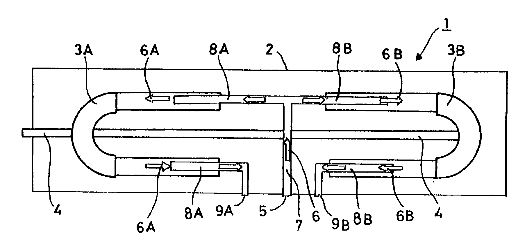
[0040]FIG. 1 is a schematic depiction showing the operating principle of an integrated device. The device 1 is a passive phase-shifter / power-splitter (or power distributor) component that comprises a housing 2, within which are housed two moving parts 3A and3B made of a conducting material placed at each end of the housing 2. Each of the moving parts 3A and 3B is capable of being subjected to a translation motion owing to a transmission bar 4 made of dielectric material, in order to provide the phase-shifting function.

[0041]An input connector 5, such as for a coaxial cable connection, is located at the center of the device 1. The electromagnetic signal 6, which enters by the input connector 5, follows the internal conductive line 7 which may be formed of a metal rod; if so, the housing 2 is conductive and constitutes the external conductor of the conductive line 7 which may be likened to a coaxial cable. The internal conductive line 7 is divided into two conductive branches 8A and 8...

second embodiment

[0063]The second embodiment depicted in FIG. 7 schematically represents the operating principle of a device 60 which is a passive phase-shifter / power-splitter (or power distributor) component. The device 60 comprises a housing 61 made of a conductive material. An input connector 62 of the electromagnetic signal is on one side of the device 60. The incoming electromagnetic signal 63 follows an internal conductive line 64, which is, for example, a hollow metal tube. A moving part 65 made of conductive material is placed in the center of the housing 61. The moving part 65 is capable of translation motion owing to a transmission bar 66 made of dielectric material which can be actuated from outside the housing 61. The moving part 65 is made up of a shared segment 67, such as a metal rod, for example, which fits into the conductive line 64. The shared segment 67 is divided into two conductive arms 68A and 68B, to serve the power-splitter function. Each of the conductive arms 68A and 68B i...


PUM


Abstract

An integrated device comprises at least one input connector (62) linked to an internal conductive line (64) and at least two output connectors (70A,70B) each respectively linked to an conductive branch (69A, 69B), wherein a single moving part (65), simultaneously serving the functions of a phase-shifter and a power-distributor, which comprises a shared segment (67) divided into two conductive arms (68A, 68B), the shared segment (67) linking the internal conductive line (64) to each of the conductive branches (69A, 69B) respectively, so as to vary, by an equal but opposite quantity, the length of the electric path between the input connector (62) and each of the output conductors (70A,70B) when the moving part (65) moves. The moving part (65) can be actuated from outside the housing, preferentially by means of a transmission bar (66).

Description

CROSS-REFERENCE[0001]This application is based on French Patent Application N° 11 55 904 filed on Jun. 30, 2011, the disclosure of which is hereby incorporated by reference thereto in its entirety, and the priority of which is hereby claimed under 35 U.S.C. §119.TECHNICAL FIELD[0002]The present invention relates to a device that provides the functions of a phase shifter and a power splitter (or power distributor) intended to be used in an antenna.BACKGROUND[0003]Panel antennas used for modern radio communications most commonly integrate electromechanical devices known as phase shifters whose purpose is to alter the antenna's electrical tilt, meaning the direction of the main lobe of the antenna's radiation pattern. Many different types of phase shifters exist. These phase-shifting devices combined with power-splitting devices are incorporated into antennas, thereby forming complete feed networks.[0004]“Trombone” phase-shifting devices are known and widely used, particularly in labor...

Claims


Application Information

Patent Timeline
Patent Type & Authority Applications(United States)
IPC IPC(8): H01P5/12H01P1/18
CPCH01P1/18H01P5/08H01Q3/32H01P1/183H01P5/183
Inventor LECAM, PATRICKHAREL, JEAN-PIERREJULIEN, THOMAS
Owner ALCATEL LUCENT SAS
Why Eureka
Try Eureka