
Method and Device for Detecting a Rotating Wheel

a technology of rotating wheels and detection methods, applied in the direction of devices using optical means, instruments, reradiation, etc., can solve problems such as detection errors, and achieve the effect of safer detection

Inactive Publication Date: 2014-08-07
KAPSCH TRAFFICCOM AG
View PDF10 Cites 24 Cited by
  • Summary
  • Abstract
  • Description
  • Claims
  • Application Information

AI Technical Summary

Benefits of technology

The patent describes a way to measure the speed of a trailer or traction vehicle by emitting a measurement beam in a slanting position. This minimizes the shadowing of the wheels and ensures safe detection of the gap between the trailer and the traction vehicle. The method also ignores horizontal components of wheel velocity and vehicle velocity to make the detection easier. Additionally, the area of incidence of the measuring beam on the vehicle is minimized to reduce parasitic spreading effects and obtain a distinct progression of the reception frequency mixture.

Problems solved by technology

Gaps between a traction vehicle and its trailer can falsely indicate signal minima and intermediate “false” maxima, which lead to an erroneous wheel detection.

Method used


Image

  • Method and Device for Detecting a Rotating Wheel
  • Method and Device for Detecting a Rotating Wheel
  • Method and Device for Detecting a Rotating Wheel

Examples


Embodiment Construction

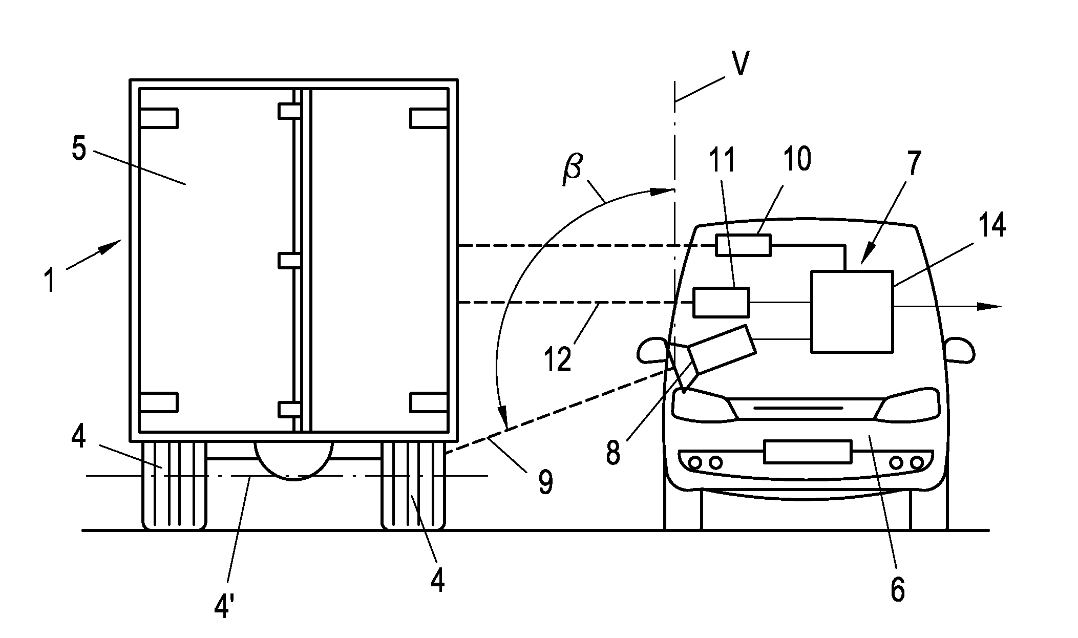
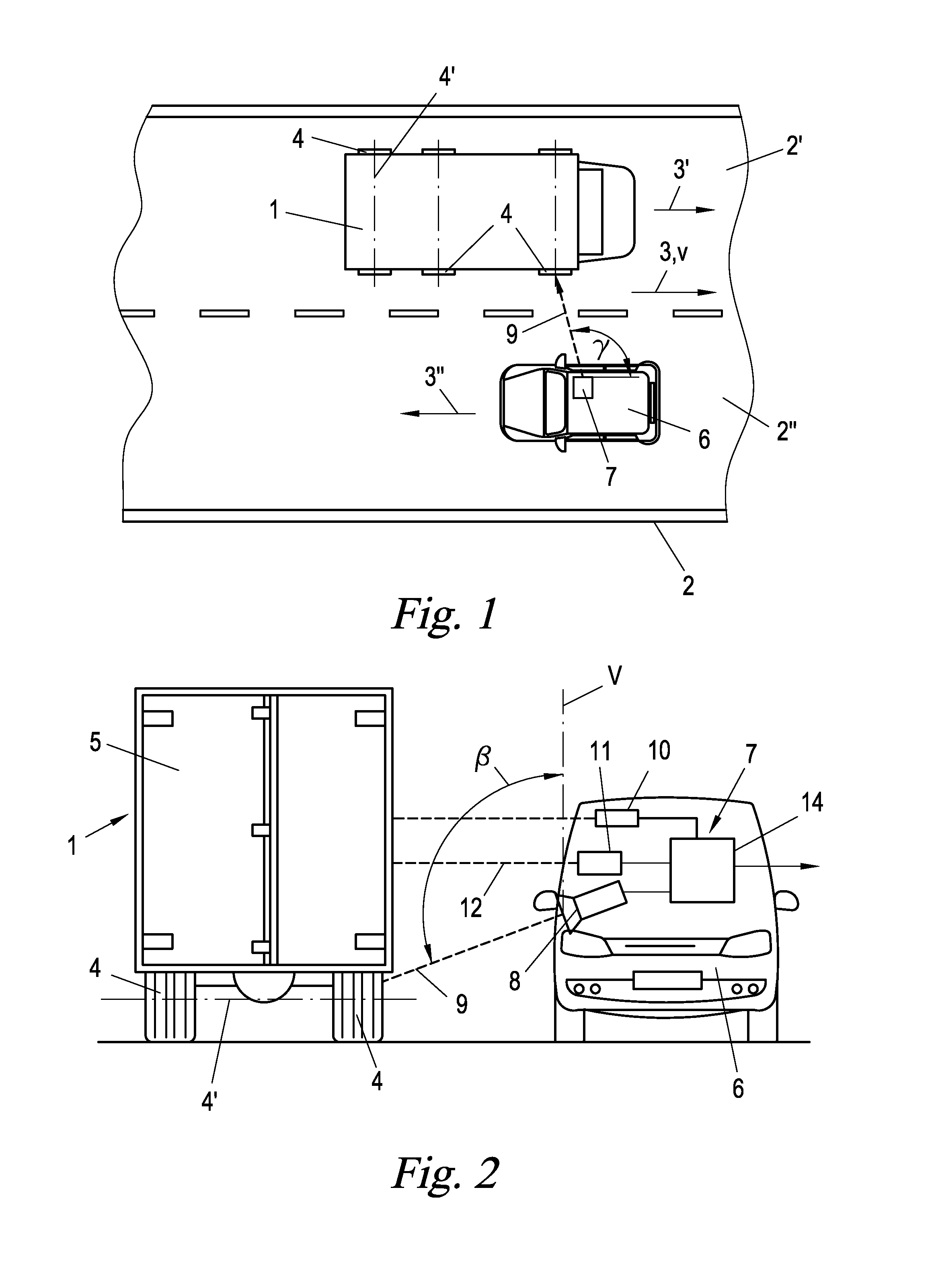
[0049]On a second lane 2″ of the roadway 2 a control vehicle 6 is moving in an opposite travel direction 3″. The travel directions 3′, 3″ may be anti-parallel, but could also be parallel, i.e. the control vehicle 6 could overtake the vehicle 1 or vice versa. The control vehicle 6 could also be stationary and the travel directions 3′, 3″ could be non-parallel; in the following the relative movement direction of the vehicle 1 with respect to the control vehicle 6 is denoted as the travel direction 3 of the vehicle 1. For simplicity it is also assumed that the travel direction 3 is approximately normal to the axles 4′ of the wheels 4 and is approximately horizontal, although this is not compulsory and deviations thereof are merely reflected in correspondingly changed projection angles of the velocity components considered in the following.

[0050]The control vehicle 6 carries a measuring apparatus 7 with a Doppler-lidar or Doppler-radar device 8 which emits an electromagnetic measuring b...


PUM


Abstract

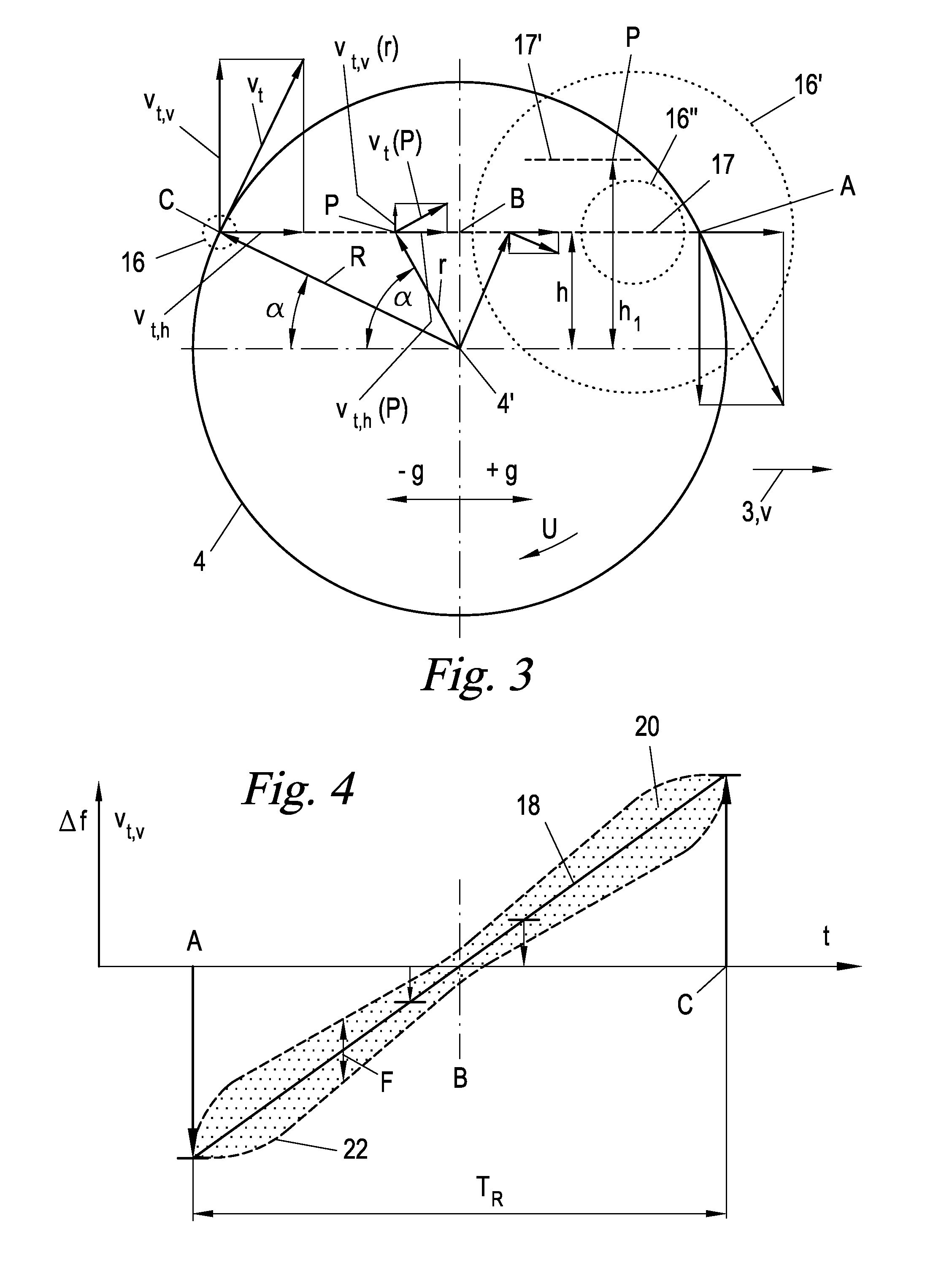
A method is described for detecting a rotating wheel of a vehicle that is travelling on a roadway in a travel direction, the wheels of which are at least partially exposed laterally, the method comprising: emitting an electromagnetic measurement beam having a known temporal progression of its frequency onto a first section above the roadway in a direction in a slant with respect to the vertical and normally or at a slant with respect to the travel direction; receiving a reflected measurement beam and recording the temporal progression of its frequencies, relative to the known progression, as a reception frequency mixture progression; and detecting a frequency band, which is continuously inclining or declining over a period of time, in the reception frequency mixture progression as a wheel. A device for conducting the method is also described.

Description

CROSS-REFERENCE TO RELATED APPLICATION(S)[0001]This application is a U.S. national phase of International Application No. PCT / EP2012 / 061645 filed Jun. 19, 2012, which designated the U.S. and claims priority to European Patent Application No. 11 450 079.6 and European Patent Application No. 11 450 080.4, the disclosures of which are herein incorporated by reference in their entireties.BACKGROUNDTechnical Field[0002]The present application relates to a method and an apparatus for detecting a rotating wheel of a vehicle that is travelling on a roadway in a travel direction, the wheels of which are at least partially exposed laterally.[0003]Detecting vehicle wheels is of interest for numerous applications. Thus it is possible to infer with certainty from the recognition of wheels that a given traffic area is being driven on in order to, for example, monitor borders or to initiate certain actions such as triggering an alarm, switching on lighting, opening a barrier, taking a picture for ...

Claims


Application Information

Patent Timeline
IPC IPC(8): G01S7/41G01S17/88G01S13/58
CPCG01S7/415G01S17/88G01S13/589G01S13/58G01S13/91G08G1/0116G08G1/04G01S13/04
Inventor STELZEN, ANDREASPICHLER, MARKUSPFEFFER, CLEMENSNAGY, OLIVERSCHEIBLHOFER, WERNERFEGER, REINHARD
Owner KAPSCH TRAFFICCOM AG
Learn More