
Radio system for long-range high-speed wireless communication

a radio system and long-range technology, applied in the direction of radiating element housings, antenna details, antennas, etc., can solve the problems of not being economically feasible to lay new fibers, not being able to extend the reach of optical fibers to sparsely populated areas, and limit the application of optical fibers, so as to increase the rigidity of the overall device/system

Active Publication Date: 2014-08-07
UBIQUITI INC
View PDF3 Cites 58 Cited by
  • Summary
  • Abstract
  • Description
  • Claims
  • Application Information

AI Technical Summary

Benefits of technology

The patent describes devices and systems for transmitting high-speed signals between points. These devices use dual high-gain reflector antennas, which have two adjacent reflectors that work together to send and receive information. The reflectors are always aligned with each other, and this alignment is fixed inside the device. This design prevents the reflectors from losing alignment, which could happen if they were not held in a rigid manner. Overall, this patent provides a way to ensure reliable and accurate transmission of high-speed signals.

Problems solved by technology

However, there are limitations to the application of optical fibers.
Because laying optical fibers in the field can require a large initial investment, it is not cost effective to extend the reach of optical fibers to sparsely populated areas, such as rural regions or other remote, hard-to-reach areas.
Moreover, in many scenarios where a business may want to establish point-to-point links among multiple locations, it may not be economically feasible to lay new fibers.
However, currently available wireless technologies for long-range, point-to-point connections encounter many problems, such as limited range and poor signal quality.

Method used


Image

  • Radio system for long-range high-speed wireless communication
  • Radio system for long-range high-speed wireless communication
  • Radio system for long-range high-speed wireless communication

Examples


Embodiment Construction

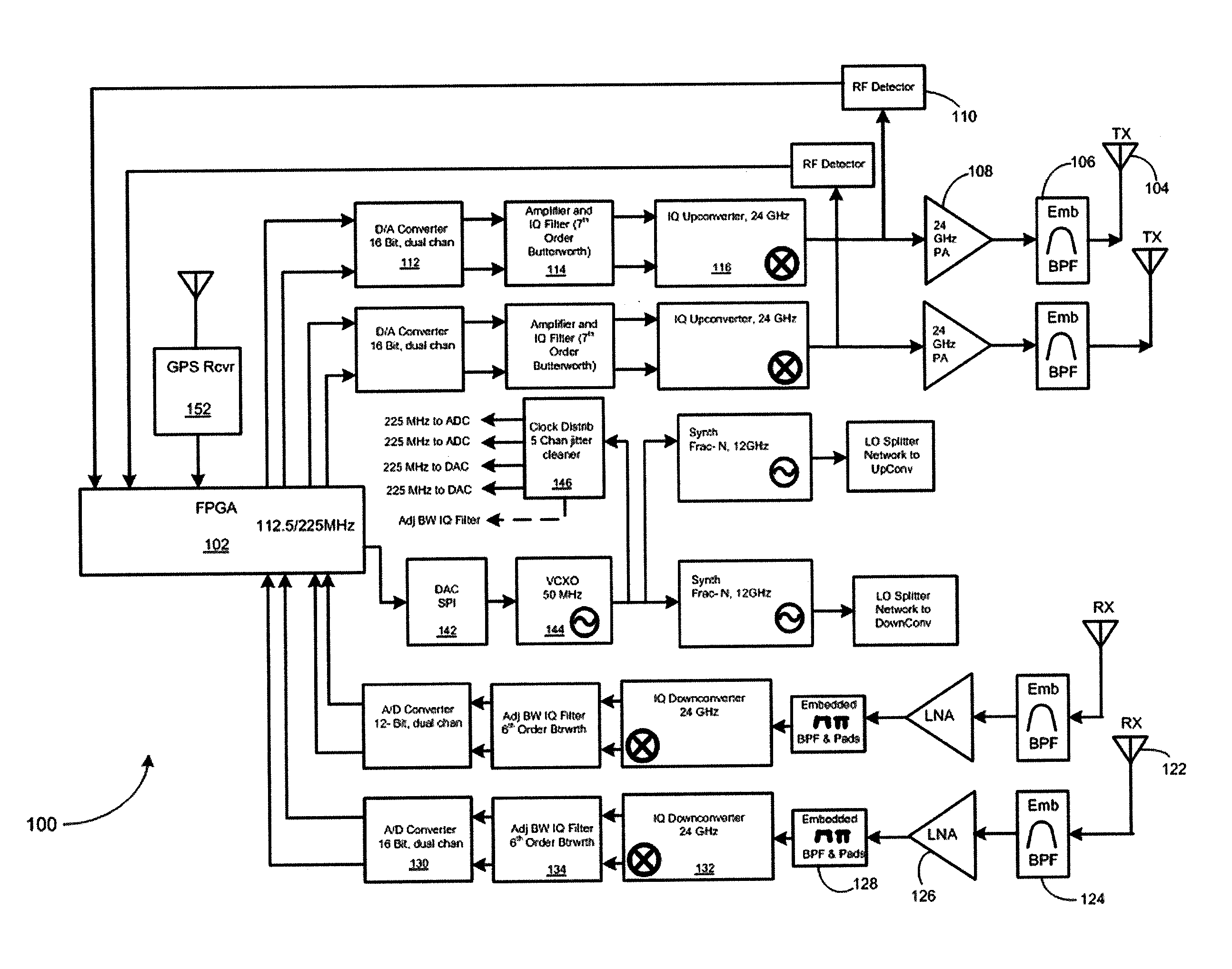
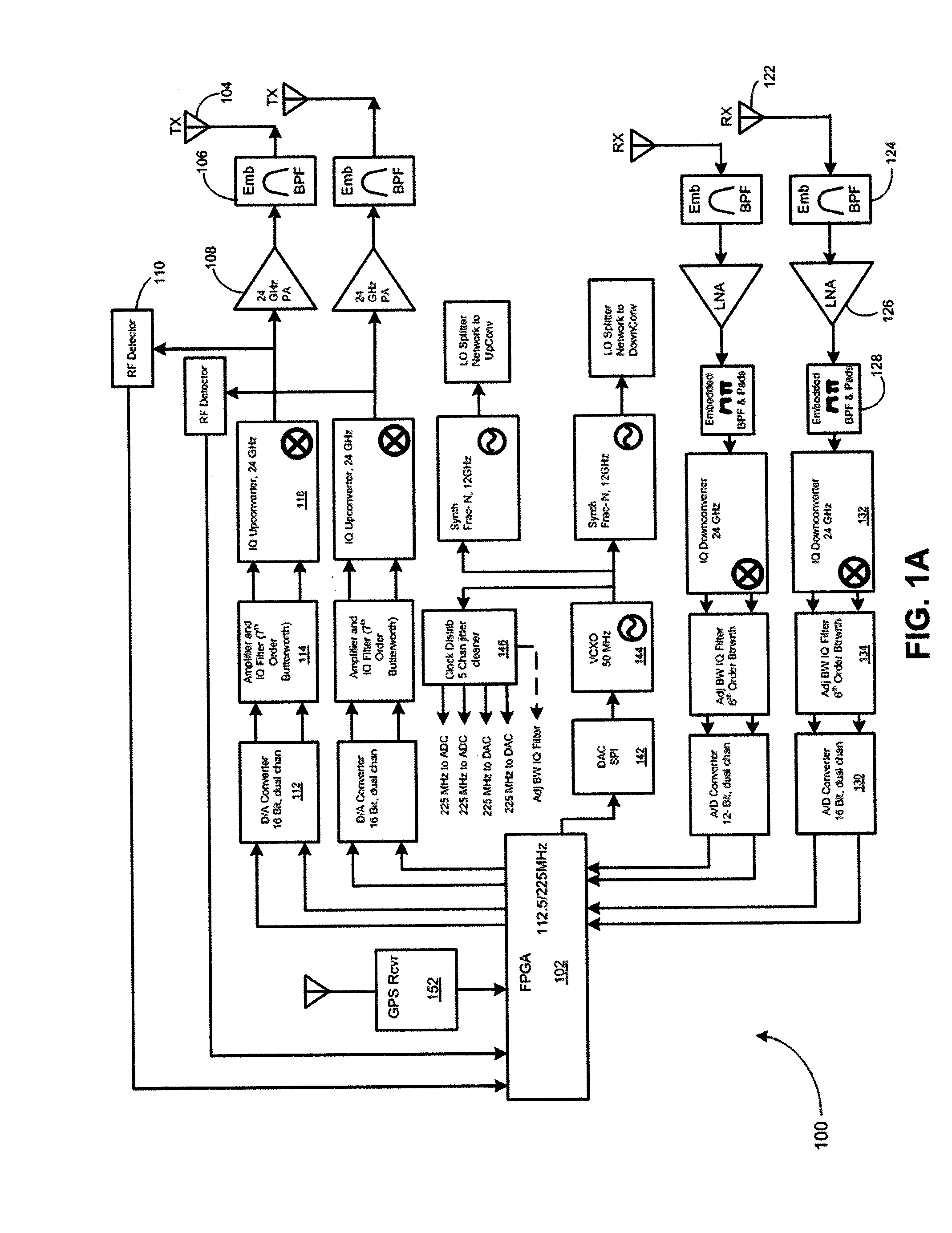
[0108]Described herein are radio devices and systems for point-to-point transmission of high bandwidth signals. These devices include radio devices / systems used for high-speed, long-range wireless communication.

[0109]In general, these radios include a dedicated transmit reflector (connected to one or more transmitters), and a dedicated receiver reflector (connected to one or more receivers). The dedicated transmit and receive reflectors are held in a fixed relationship with each other so that they are aimed directionally parallel with each other. In some variations the devices and systems may also be configured so that the circuitry for the radio is held on a single board, which connects to both the transmitter antenna feed, connected to the transmitter reflector, and the receiver antenna feed, connected to the receiver reflector. In some variations the two reflectors may overlap, e.g., so that the transmitter reflector (e.g., a parabolic reflector) cuts into the receiver reflector....


PUM


Abstract

Devices and systems, and methods of using them, for point-to-point transmission / communication of high bandwidth signals. Radio devices and systems may include a pair of reflectors (e.g., parabolic reflectors) that are adjacent to each other and configured so that one of the reflectors is dedicated for sending / transmitting information, and the adjacent reflector is dedicated for receiving information. Both reflectors may be in a fixed configuration relative to each other so that they are aligned to send / receive in parallel. In many variations the two reflectors are formed of a single housing, so that the parallel alignment is fixed, and reflectors cannot lose alignment. The device / systems may be configured to allow switching between duplexing modes. These devices / systems may be configured as wide bandwidth zero intermediate frequency radios including alignment modules for automatic alignment of in-phase and quadrature components of transmitted signals.

Description

CROSS REFERENCE TO RELATED APPLICATIONS[0001]This patent application claims priority to: U.S. provisional patent application 61 / 762,814, filed Feb. 8, 2013, titled “RADIO SYSTEM FOR LONG-RANGE HIGH-SPEED WIRELESS COMMUNICATION”; and U.S. provisional patent application No. 61 / 760,381, filed Feb. 4, 2013, and titled “FULL DUPLEX ANTENNA”. The entire content of each of these applications is herein incorporated by reference in their entirety.INCORPORATION BY REFERENCE[0002]All publications and patent applications mentioned in this specification are herein incorporated by reference in their entirety to the same extent as if each individual publication or patent application was specifically and individually indicated to be incorporated by reference.FIELD[0003]This disclosure is generally related to wireless communication systems. More specifically, this disclosure is related to radio systems for high-speed, long-range wireless communication, and particularly radio devices for point-to-poi...

Claims


Application Information

Patent Timeline
Patent Type & Authority Applications(United States)
IPC IPC(8): H01Q15/16
CPCH01Q15/16H01Q1/1228H01Q1/42H01Q3/26H01Q3/267H01Q19/134
Inventor SCHULZ, GARY D.ODLYZKO, PAULSANFORD, JOHN R.FAY, CHRISTOPHERLEE, JUDEMACENSKI, CHARLES D.KENIUK, RICHARD J.LASCARI, LANCE D.
Owner UBIQUITI INC
Learn More