Fixing device and image forming apparatus including same

Active Publication Date: 2014-08-07
RICOH KK
View PDF3 Cites 23 Cited by
  • Summary
  • Abstract
  • Description
  • Claims
  • Application Information

AI Technical Summary

Benefits of technology

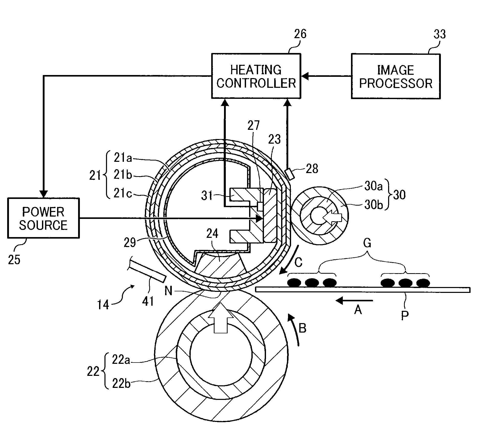
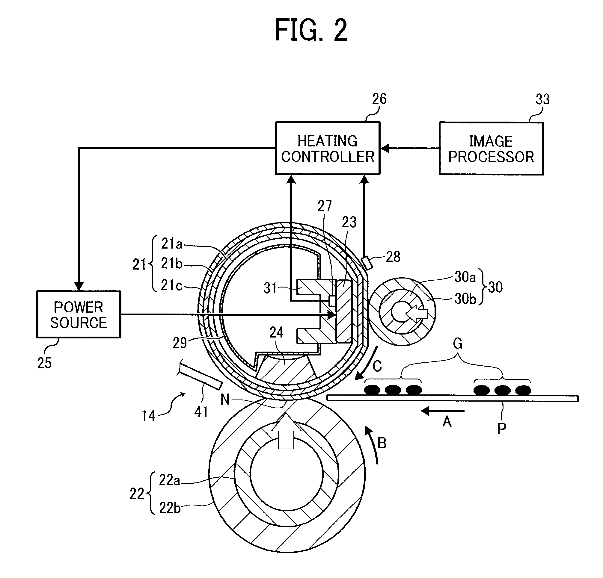
[0010]In at least one embodiment of this disclosure, there is provided a fixing device including a fixing rotary body, an opposed member, a heater, and a heating controller. The opposed member opposes the fixing rotary body to form a nipping portion between the opposed member and the fixing rotary body. The heater heats the fixing rotary body. The heater includes plural heat generators arranged in a width direction of a recording medium fed to the nipping portion. The heating controller separately controls outputs of the heat generators. When the recording medium fed to the nippin

Problems solved by technology

However, when an image is placed on only a portion of the sheet, heat energy is wasted in a non-image area, i.e., an area having no image.
However, such a

Method used


Image

  • Fixing device and image forming apparatus including same
  • Fixing device and image forming apparatus including same
  • Fixing device and image forming apparatus including same

Examples


Example

[0041]The accompanying drawings are intended to depict embodiments of the present invention and should not be interpreted to limit the scope thereof. The accompanying drawings are not to be considered as drawn to scale unless explicitly noted.

DETAILED DESCRIPTION OF EMBODIMENTS

[0042]In describing embodiments illustrated in the drawings, specific terminology is employed for the sake of clarity. However, the disclosure of this patent specification is not intended to be limited to the specific terminology so selected and it is to be understood that each specific element includes all technical equivalents that operate in a similar manner and achieve similar results.

[0043]Although the embodiments are described with technical limitations with reference to the attached drawings, such description is not intended to limit the scope of the invention and all of the components or elements described in the embodiments of this disclosure are not necessarily indispensable to the present invention....


PUM


Abstract

A fixing device includes a fixing rotary body, an opposed member, a heater, and a heating controller. The opposed member opposes the fixing rotary body to form a nipping portion therebetween. The heater includes heat generators arranged in a width direction of a recording medium. When the recording medium fed to the nipping portion has an image area and a non-image area, the heating controller controls the outputs of the heat generators based on image information so that a first heat generator of the heat generators corresponding to the image area is higher in temperature and a second heat generator of the heat generators corresponding to the non-image area is lower in temperature. Based on information other than the image information, the heating controller temporarily shifts an area of the fixing rotary body corresponding to the non-image area to a temperature differing from a normal temperature.

Description

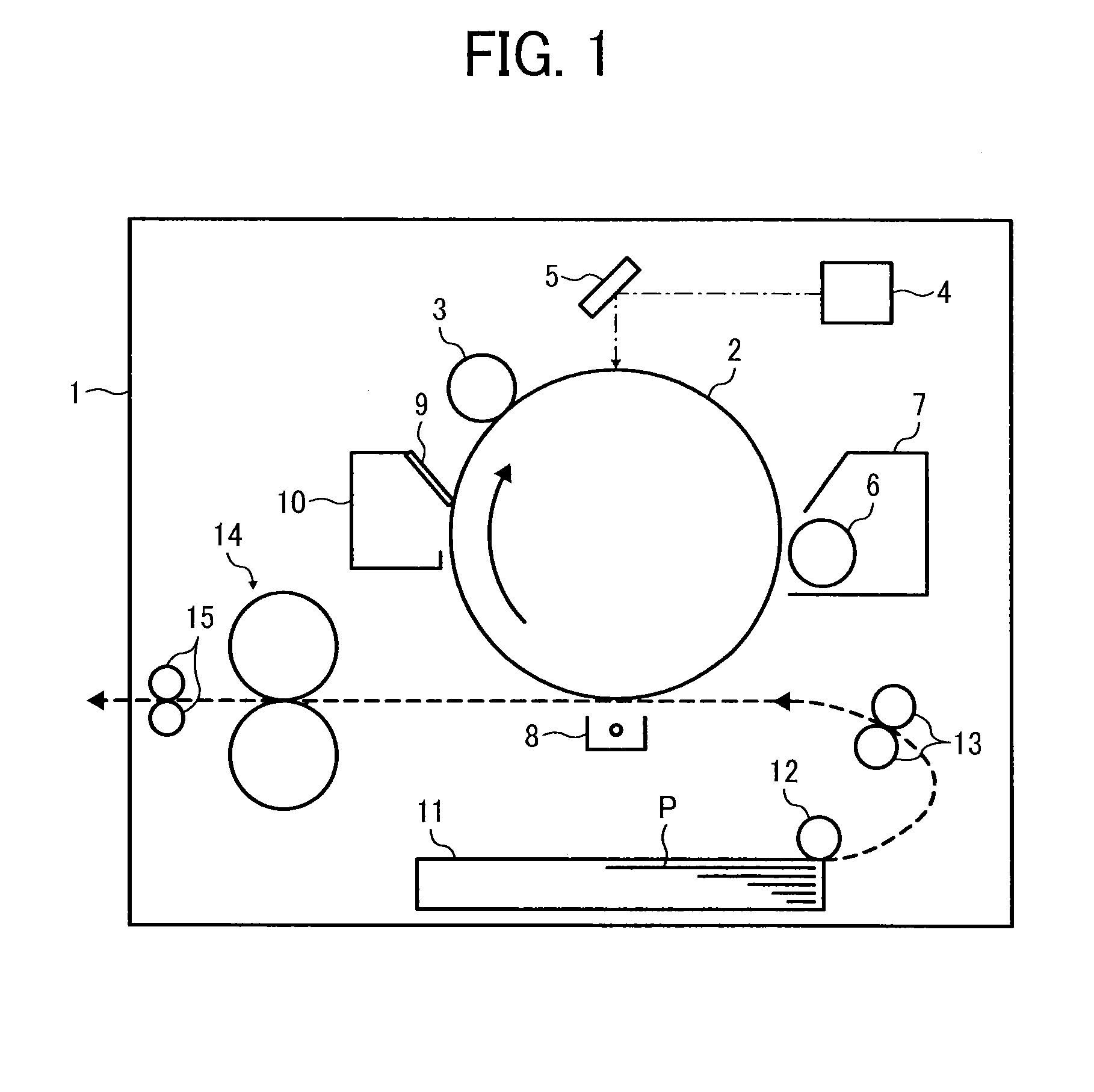
CROSS-REFERENCE TO RELATED APPLICATIONS[0001]This patent application is based on and claims priority pursuant to 35 U.S.C. §119 to Japanese Patent Application Nos. 2013-022326, filed on Feb. 7, 2013, and 2013-261337, filed on Dec. 18, 2013, in the Japan Patent Office, the entire disclosure of each of which is hereby incorporated by reference herein.BACKGROUND[0002]1. Technical Field[0003]Embodiments of the present invention relate to a fixing device to fix an image on a recording medium and an image forming apparatus including the fixing device.[0004]2. Description of the Related Art[0005]Image forming apparatuses are used as, for example, copiers, printers, facsimile machines, and multi-functional devices having at least one of the foregoing capabilities. As one type of image forming apparatus, electrophotographic image forming apparatuses are known. Such electrophotographic image forming apparatuses may have a fixing device to fix a toner image on a sheet of paper serving as a rec...

Claims


Application Information

Patent Timeline
IPC IPC(8): G03G15/20
CPCG03G15/2039G03G2215/2035
Inventor SAMEI, MASAHIROWAIDA, TAKUMIONO, HIROSHIYAMAMOTO, TAKESHIFUJIMOTO, IPPEISEO, HIROSHIISHIGAYA, YASUNORIKISHI, KAZUHITOYAMASHINA, RYOTA
Owner RICOH KK
Why Eureka
Try Eureka