Compressor

a compression device and compression tube technology, applied in the field of compression devices, can solve problems such as seizures between the rear portion and the rear bearing

Active Publication Date: 2014-08-07
DAIKIN IND LTD
View PDF2 Cites 8 Cited by
  • Summary
  • Abstract
  • Description
  • Claims
  • Application Information

AI Technical Summary

Benefits of technology

[0055]According to the compressor of the invention, the diameter of the rear shaft of the shaft is smaller than the diameter of the front shaft of the shaft, and the rigidity of the rear-side elastic portion is smaller than the rigidity of the front-side elastic portion. Therefore, the bearing pressure between the rear shaft of the shaft and the rear bearing can be reduced, so that seizures between the rear shaft and the rear bearing can be prevented.

Problems solved by technology

As a result, the bearing pressure between the rear portion and the rear elastic portion is increased, causing seizures between the rear portion and the rear bearing.

Method used


Image

  • Compressor
  • Compressor
  • Compressor

Examples


first embodiment

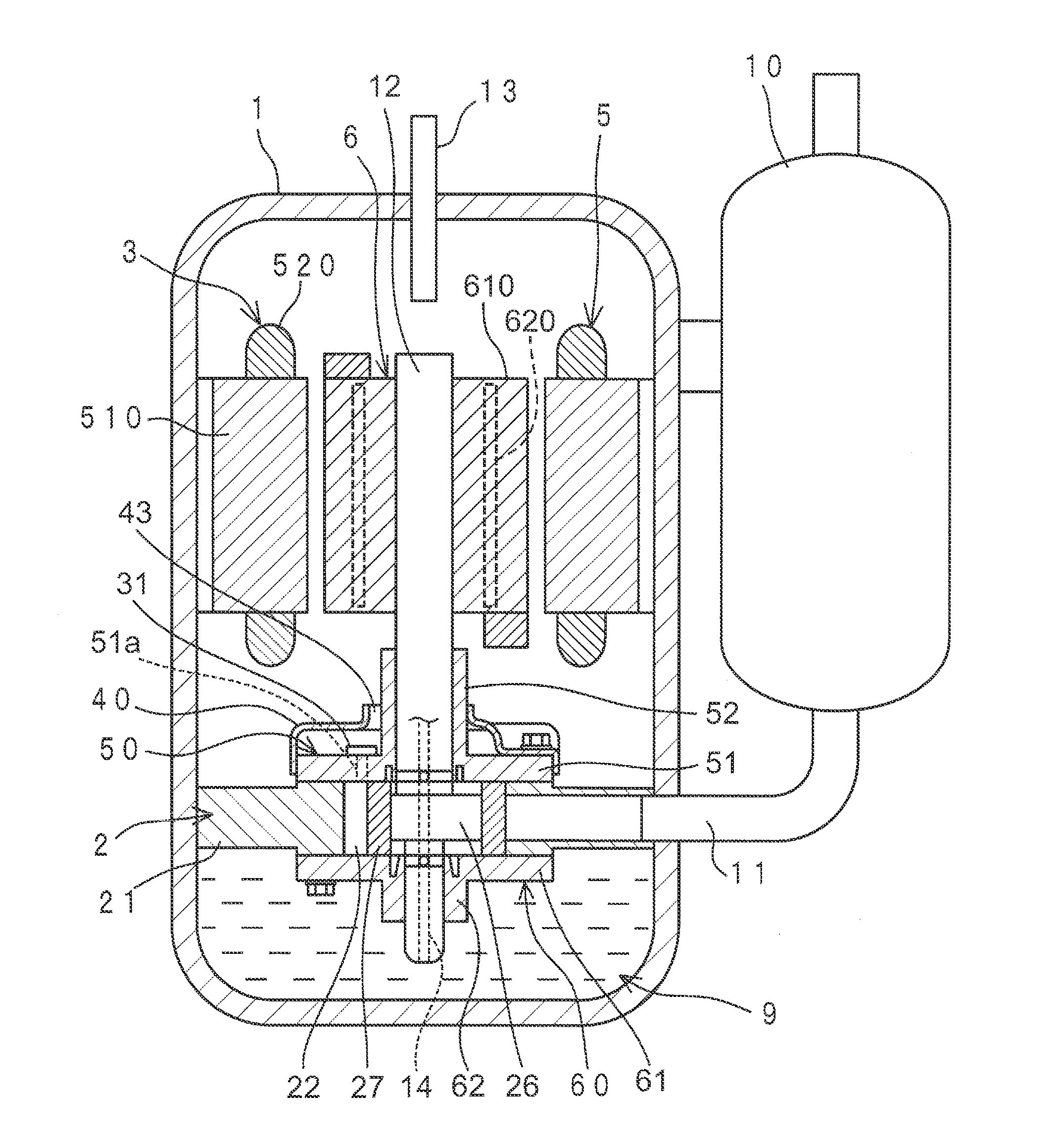
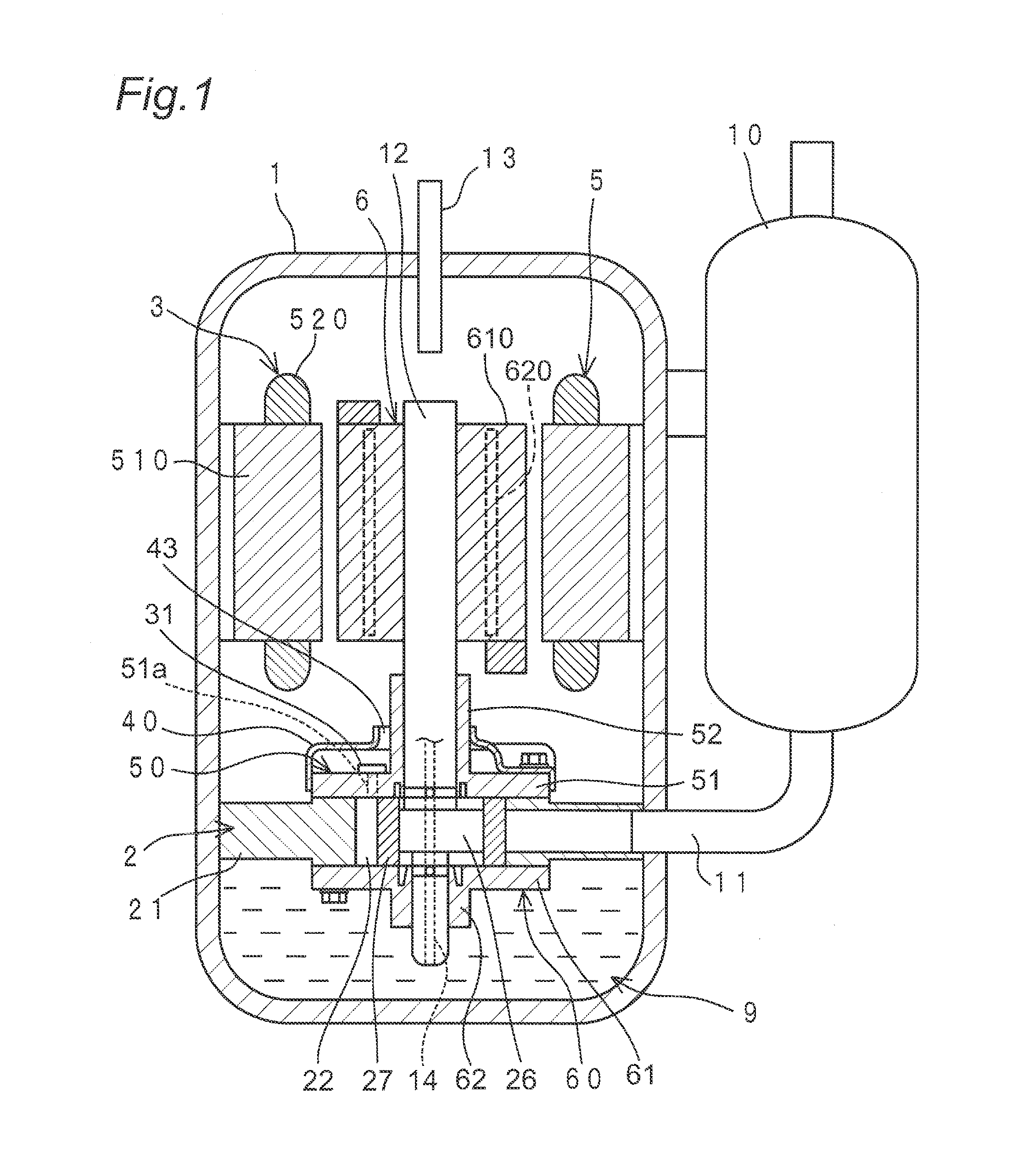
[0060]FIG. 1 is a longitudinal sectional view showing a first embodiment of the compressor according to the invention. This compressor includes a closed container 1, a compression element 2 placed in the closed container 1, and a motor 3 placed in the closed container 1 to drive the compression element 2 via a shaft 12.

[0061]The compressor, which is a so-called vertically positioned high-pressure dome type rotary compressor, is placed in the closed container 1 with the compression element 2 below and the motor 3 above. By a rotor 6 of the motor 3, the compression element 2 is driven via the shaft 12.

[0062]The compression element 2 sucks in a refrigerant gas from an accumulator 10 through a suction pipe 11. This refrigerant gas is obtained by controlling a condenser, an expansion mechanism and an evaporator which are not shown and which make up an air conditioner as an example of a refrigeration system in combination with this compressor. Carbon dioxide is used as the refrigerant, bu...

second embodiment

[0099]FIG. 3 shows a second embodiment of the compressor according to the invention. This second embodiment differs from the first embodiment in terms of the cylinder quantity. In this second embodiment, like reference signs designate like constituent members in conjunction with the first embodiment and so their description is omitted.

[0100]As shown in FIG. 3, this compressor is a two-cylinder compressor, in which a compression element 2A includes the front bearing 50, the rear bearing 60, a first cylinder 121, an intermediate member 170 and a second cylinder 221 placed between the front bearing 50 and the rear bearing 60, a first roller 127, and a second roller 227.

[0101]The first cylinder 121, the intermediate member 170 and the second cylinder 221 are placed in order along a shaft 12 from the front bearing 50 side toward the rear bearing 60 side.

[0102]The first cylinder 121 is sandwiched between the front bearing 50 and the intermediate member 170. A first cylinder chamber 122 of...


PUM


Abstract

A compressor includes a closed container housing a compression element driven by the shaft of a motor. The compression element includes a first and second bearings supporting first and second shaft portions, and at least one cylinder having at least one cylinder chamber disposed between the first and second bearings. At least one roller is fitted to the shaft in the at least one cylinder chamber. The first bearing is disposed closer to the motor than the second bearing. The first and second bearings have first and second annular grooves opened to the at least one cylinder chamber and first and second elastic portions provided in first and second opposing surfaces, respectively. A diameter of the second shaft portion is smaller than a diameter of the first shaft portion. A rigidity of the second elastic portion is smaller than a rigidity of the first elastic portion.

Description

TECHNICAL FIELD[0001]The present invention relates to a compressor to be used in, for example, air conditioners, refrigerators and the like.BACKGROUND ART[0002]Conventionally, there has been provided a compressor which includes a closed container, a compression element to be placed in the closed container, and a motor placed in the closed container to drive the compression element via a shaft (see PTL1: JP S55-69180 U).[0003]Conventionally, the compression element includes a front bearing and a rear bearing for supporting a shaft, and a cylinder to be placed between the front bearing and the rear bearing. The front bearing is placed closer to the motor than the rear bearing. The diameter of a front portion of the shaft supported by the front bearing is equal to the diameter of a rear portion of the shaft supported by the rear bearing.[0004]A front annular groove and an annular-shaped front elastic portion positioned radially inward of the front annular groove are provided in a surfa...

Claims


Application Information

Patent Timeline
Patent Type & Authority Applications(United States)
IPC IPC(8): F04B35/00
CPCF04B35/00F04B39/0246F04B39/0253F04C18/356F04C23/008F04C29/0021F04C2240/601
Inventor KANAYAMA, TAKEHIROTOMIOKA, NAOTOWATANABE, YUUICHIROU
Owner DAIKIN IND LTD
Why Eureka
Try Eureka