Cross joint

a cross-joint and needle bearing technology, applied in the direction of engine components, mechanical devices, couplings, etc., can solve the problems of noise emission, rise in manufacturing costs, and difficulty in bringing the spherical protrusion provided on the inner surface of the cup of the needle bearing into contact with the conical hole of the spider shaft with a proper pre-load, so as to avoid noise emission, smooth steering feeling, and reduce manufacturing costs

Inactive Publication Date: 2006-10-10
NSK LTD
View PDF21 Cites 1 Cited by
  • Summary
  • Abstract
  • Description
  • Claims
  • Application Information

AI Technical Summary

Benefits of technology

[0021]Thus, according to the present invention, the needle bearing and the spider shaft are interference-fitted to each other, and it is therefore feasible to reliably prevent the emission of noises due to the interference between the spider shaft and the needle bearing without bringing about any rise in manufacturing cost.
[0022]In addition, the rollers in the bearing cup of the needle bearing are so structured as t...

Problems solved by technology

According to the structure disclosed in Patent Application Laid-Open No. 2000-170786, however, if a dimensional accuracy of each component is low, when the cross joint is assembled to the yokes, it is difficult to bring the spherical protrusion provided on the inner surface of the cup of the needle bearing into contact with the conical hole of the spider shaft with a proper pre-load.
As a result, a minute gap between the spider shaft and the needle bearing can not be kept uniform, resulting in an ...

Method used


Image

  • Cross joint
  • Cross joint
  • Cross joint

Examples


first embodiment

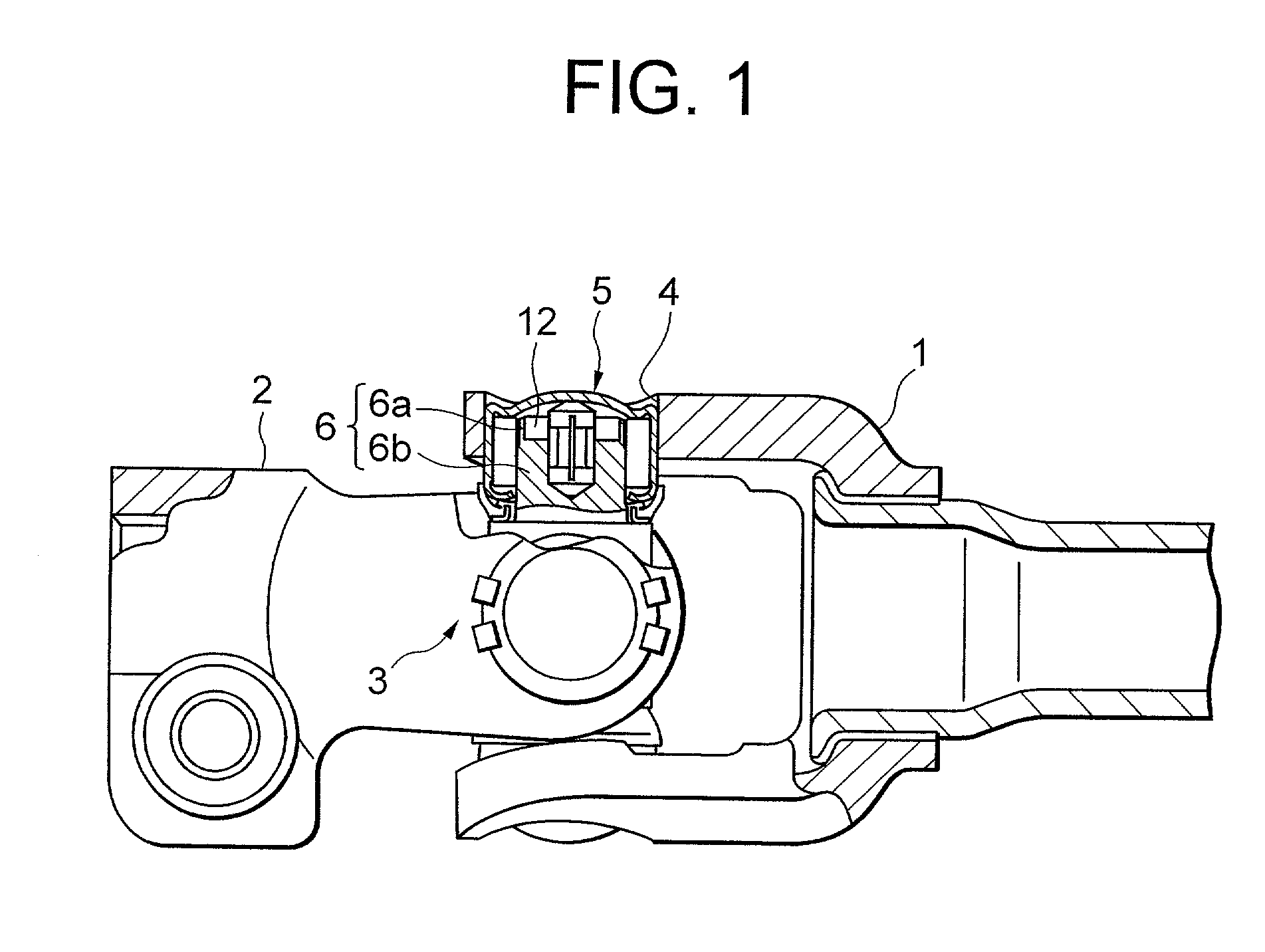
[0039]FIG. 1 is a side view including a partially cut-off section, showing a cross joint in a first embodiment of the present invention. FIG. 2 is a sectional view of the cross joint illustrated in FIG. 1.

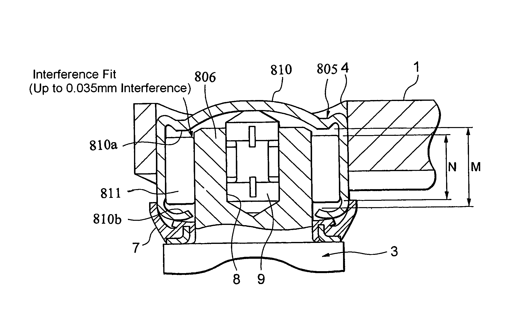
[0040]As shown in FIG. 1, the cross joint has a cross-shaped spider 3 interposed between a pair of yokes 1 and 2. To be more specific, as shown in FIG. 2, a spider shaft 6 is rotatably fitted into a bearing hole 4 of the yoke 1 through a needle bearing 5. A seal member 7 is provided along an outer periphery of a lower portion of the spider shaft 6. The yoke may be manufactured by any one of sheet metal working, forging and casting and composed of any one of ferro-series and alumi-series materials.

[0041]Further, a pin 9 composed of a synthetic resin is inserted into an axial hole 8 formed in an axial core of the spider shaft 6. The needle bearing 5 is provided with a metallic cup 10 fitted in the bearing hole 4. A plurality of rolling members (rollers) 11 are arranged inwardly of th...

second embodiment

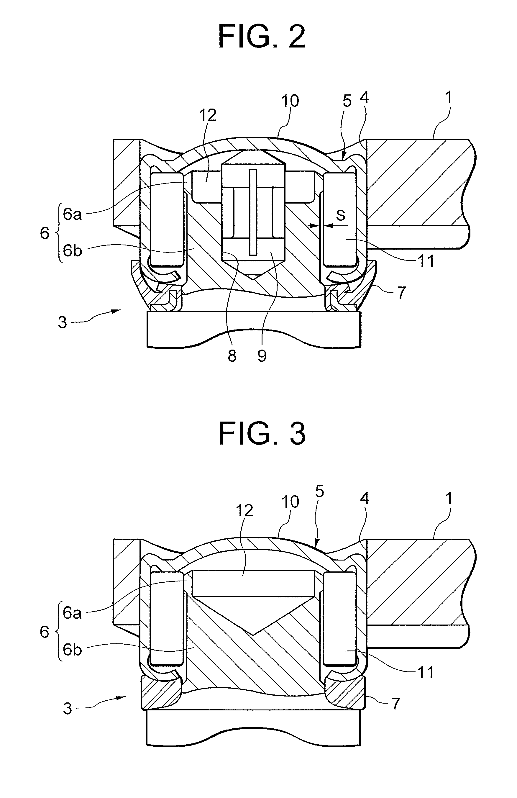
[0049]FIG. 3 is a sectional view showing a cross joint in a second embodiment of the present invention according to the second embodiment, the synthetic resin pin 9 is not provided, and therefore the bottomed hole 112 takes a conical shape, which leads to a less cost than in the first embodiment.

[0050]The cross joint in the second embodiment is, however, limited to the use in the driving room. Further, the seal member 107 is composed of a nitrile rubber. Other configurations and operations are the same as those in the first embodiment.

third embodiment

[0051]FIG. 4 is a sectional view showing a cross joint in a third embodiment of the present invention. According to the third embodiment, the contact portion of the spider shaft is formed as a separate member. Namely, the spider shaft 206 is formed with an axial hole 13, and a separate spacer 14 is fitted into this axial hole 13.

[0052]A protrusion 14a of this spacer 14 is press-fitted into the axial hole 13, and a thin ring-shaped portion 14b of the spacer 14 functions as the contact portion 6a in the first and second embodiments does. According to the third embodiment, the grinding of the outside diametric portion of the spider is easier than in the first and second embodiments. Other configurations and operations are the same as those in the first embodiment.


PUM


Abstract

A cross joint comprises yokes each formed with a bearing hole and a spider shaft rotatably fitted into the bearing hole through a rolling bearing. The spider shaft is formed with a contact portion with the rolling bearing, the contact portion having its outside diameter larger than an outside diameter of the spider shaft.

Description

[0001]This application claims the benefit of Japanese Patent Applications No. 2000-371934, 2001-219935, 2001-313941 and 2001-313945 which are hereby incorporated by reference.BACKGROUND OF THE INVENTION[0002]1. Field of the Invention[0003]The present invention relates to a cross joint used for a steering apparatus for, e.g., a vehicle.[0004]2. Related Background Art[0005]In the steering apparatus for the vehicle, a cross joint constructed of a pair of yokes and a cross-shaped spider and serving to propagate a torque in a way that rotates a predetermined bending angle, is interposed between, for instance, an upper shaft and a lower shaft of a steering shaft.[0006]According to a cross joint disclosed in, e.g., Japanese Patent Application Laid-Open No. 2000-170786, a shaft member of the spider is fitted into a bearing hole of a yoke through a needle bearing, such that said shaft member is capable of oscillating. A spherical protrusion formed on an axial core of an inner surface of a cu...

Claims


Application Information

Patent Timeline
IPC IPC(8): F16D3/41
CPCF16C21/005F16D3/41F16C2361/41F16D3/385
Inventor SEKINE, HIROSHI
Owner NSK LTD
Why Eureka
Try Eureka