Noise treatment method and system for paper mill

A technology for noise treatment and paper mills, applied to components of pumping devices for elastic fluids, non-variable-capacity pumps, pump components, etc.

Active Publication Date: 2022-07-26
SICHUAN QIANWEI FENGSHENG PAPER LLC
View PDF0 Cites 0 Cited by
  • Summary
  • Abstract
  • Description
  • Claims
  • Application Information

AI Technical Summary

Problems solved by technology

[0003] In the prior art, certain silencing equipment will be installed on the air outlet of the fan. These silencing equipment include a silencing pipe, and a plurality of silencing holes are arranged on the silencing pipe. Since the air blown by the fan contains more dust particles, these silencing equipment Dust particles will block the sound-absorbing hole, thus affecting the sound-absorbing and noise-reducing effect of the sound-absorbing equipment

Method used


Image

  • Noise treatment method and system for paper mill
  • Noise treatment method and system for paper mill
  • Noise treatment method and system for paper mill

Examples


Embodiment 1

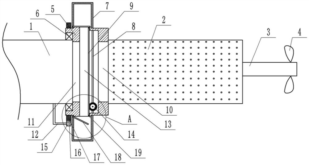
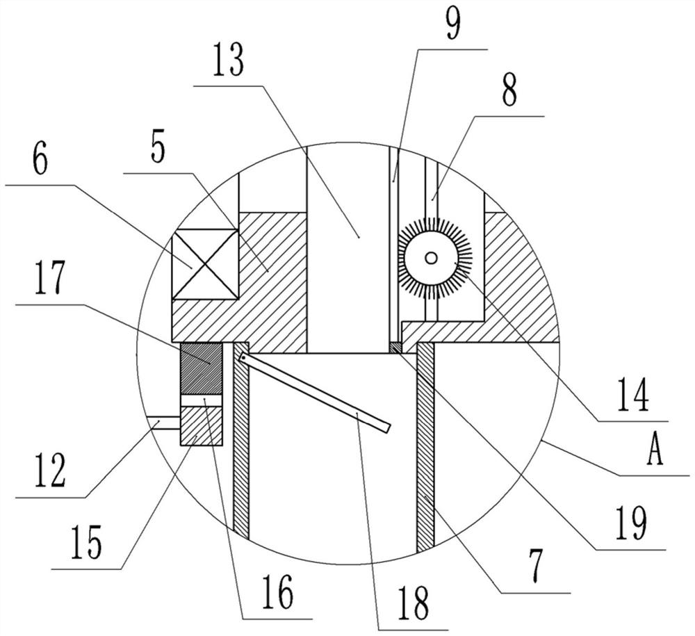
[0029] basically as attached figure 1Shown: The noise treatment system used in paper mills includes a muffler pipe 2 and a rotating sleeve 5. The left end of the muffler pipe 2 is fixedly connected to the rotating sleeve 5. The specific fixing method is: the left end of the muffler pipe 2 is welded with a flange plate , bolts are connected between the flange plate and the rotating sleeve 5. The rotating sleeve 5 is provided with an air inlet 11 for communicating with the air outlet pipe 1 of the fan and an air outlet 10 for communicating with the muffler pipe 2. The air inlet 11 is located on the left side of the air outlet 10, and the rotating sleeve 5 is rotated through the bearing 6. Connect it to the outlet duct 1 of the fan. The interior of the rotating sleeve 5 is provided with a dust filter cavity 13, the dust filter cavity 13 is located on both sides of the air inlet 11 and the air outlet 10, the dust filter cavity 13, the air inlet 11 and the air outlet 10 are connec...

Embodiment 2

[0040] combine Figure 4-Figure 5 As shown, the outer side of the rotating sleeve 5 is fixed with a plurality of telescopic rods 20 by screws, the circumference of the multiple telescopic rods 20 is evenly distributed on the rotating sleeve 5, and the end of the telescopic rod 20 away from the rotating sleeve 5 is fixedly connected with an iron ball 21 by screws, The telescopic rod 20 in this embodiment includes two sleeves that are sleeved with each other. A tension spring is arranged inside the telescopic rod 20, and both ends of the tension spring are welded to the iron ball 21 and the rotating sleeve 5 respectively, so that the telescopic rod 20 is in the Under normal conditions, it is in a state of contraction under the action of the tension spring. combine Figure 5 As shown, the outer side of the rotating sleeve 5 is provided with a magnet 24 for attracting the iron ball 21, the magnet 24 is fixed on the air outlet duct 1 of the fan through the frame body, and the magn...


PUM


Abstract

The invention relates to the field of paper processing, in particular to a noise treatment system for a paper mill, comprising a muffler pipe, one end of the muffler pipe is provided with a rotating sleeve for being rotatably connected to an air outlet pipe of a fan, and the rotating sleeve is provided with a rotating sleeve for The air inlet communicated with the air outlet pipe of the fan and the air outlet used to communicate with the muffler pipe, the rotating sleeve is provided with a dust filter cavity, the dust filter cavity, the air inlet and the air outlet are connected, and a filter screen is arranged in the dust filter cavity. In addition, the present invention also improves a processing method using the above-mentioned processing system. Through the present invention, the noise reduction effect of the paper mill is improved.

Description

technical field [0001] The invention relates to the field of paper processing, in particular to a noise processing method and system for a paper mill. Background technique [0002] During the processing of toilet paper, a lot of equipment and devices are needed to complete it. For example, in the paper processing and production, it is necessary to use bamboo chip cleaning devices, rappers, pulp mixers, recovery boiler dust collectors, and various fans. During the operation of these equipments, noise will inevitably occur. For example, the equipments collide and rub against each other during operation, and the wind blown by the fan contains certain noise. These noises seriously affect the living environment of factory workers and nearby residents. Brings noise pollution to them. Most of these noises in paper mills are emitted by fans such as blowers and ventilators. Therefore, reducing the noise of fans plays a key role in reducing the noise of the entire paper mill. [000...

Claims


Application Information

Patent Timeline
Patent Type & Authority Patents(China)
IPC IPC(8): F04D25/08F04D29/66F04D29/70F04D27/00
CPCF04D25/08F04D29/667F04D29/703F04D27/004
Inventor 杨朝林周传平申群林
Owner SICHUAN QIANWEI FENGSHENG PAPER LLC
Why Eureka
Try Eureka