Odour seal for a vacuum toilet drain system

a vacuum toilet and drain system technology, applied in the direction of sewage draining, aircraft crew accommodation, functional valve types, etc., can solve the problem of not being able to use vacuum systems involving high volume flows, and achieve the effect of preventing any fluttering with associated noise emissions, faster and more reliable opening of the odour seal, and reducing the risk of fluttering

Active Publication Date: 2014-01-07
AIRBUS OPERATIONS GMBH
View PDF14 Cites 3 Cited by
  • Summary
  • Abstract
  • Description
  • Claims
  • Application Information

AI Technical Summary

Benefits of technology

[0006]An exemplary embodiment of the invention is based on the generic state of the art by providing an odour seal for a vacuum toilet drain system whose cross section in the state of no throughflow tapers off in such a way in the downstream direction that the interior walls on the downstream end of the odour seal rest against each other so that the odour seal in a downstream direction allows throughflow while in the opposite direction it blocks throughflow, wherein the downstream end of the odour seal is closed in the state of throughflow and no throughflow of the odour seal. In this arrangement, terms such as “downstream” or “upstream” refer to the intended installation positioning of the odour seal. The flow resistance caused as a result of the tapering off of the cross section on the downstream end of the odour seal results in the odour seal distending during the suction removal process, thus assuming a defined stable geometry which is maintained during the entire suction removal process, which stable geometry prevents any fluttering with associated noise emissions. This exemplary embodiment may thus provide an odour seal which at first makes possible odour-free and silent outflow of fluid (in particular a liquid medium) in the provided flow direction through the odour seal without there being a pressure differential between the odour seal entry and the odour seal exit, and during the flushing process makes it possible to remove fluid (in gaseous or liquid form) by vacuum suction without or less odour or noise, in which vacuum suction on the exit side lower pressure is present at the odour seal than is the case on the entry side. The closing or sealing at the downstream end of the odour seal causes the flow resistance in the downstream direction to be further increased which in turn results in faster and more reliable opening of the odour seal in the downstream direction. Furthermore, fluttering of the downstream end during the suction removal process is reliably prevented. In the upstream direction thus more reliable blockage may be achieved because it is impossible for the gases or odours arising from the waste water system to move upstream through the odour seal.
[0007]According to a further exemplary embodiment, the odour seal is produced from a material that is selected from the group comprising Teflon, latex, silicon, caoutchouc or a mixture of these. These materials are essentially resistant to alkaline solutions, acid solutions and saltwater and provide good flexibility and long-term stability, even with frequent movement, as well as good ageing stability.
[0010]According to a further exemplary embodiment, a drainage device is provided which comprises an odour seal according to one of the preceding exemplary embodiments and comprises a sieve which is arranged upstream of the odour seal. By means of such a sieve a large input of dirt into the odour seal may be prevented, which would otherwise possibly cause a blockage of the odour seal.
[0011]According to a further exemplary embodiment, a drainage device is provided which comprises an odour seal in which in a region in which in the state of no throughflow the interior walls rest against each other there is at least one opening in a wall of the odour seal, and further comprises a sieve whose through-apertures are smaller than the apertures in the wall of the odour seal. As a result of the apertures of the sieve being smaller than the apertures in the odour seal, the input of dirt of a size that it cannot move through the openings of the odour seal may be prevented which reliably prevents blocking of the odour seal.
[0012]According to a further exemplary embodiment, a vacuum toilet system for an aircraft with an odour seal or a drainage device according to one of the preceding exemplary embodiments is provided. Such a vacuum toilet system may provide an advantage in that as a result of the very simple design of the odour seal it is possible to do without expensive means (e.g. controlled valves, etc.) to reduce noise emissions, and the vacuum toilet system is thus more economical and easier to produce and is also lighter in weight.
[0013]According to a further exemplary embodiment, an aircraft comprising such a vacuum toilet system is provided, which may be advantageous in that as a result of the simple design it is possible to save weight—a very significant factor in the context of aircraft.

Problems solved by technology

However, the embodiments of these odour seals from stationary sanitary applications are designed only for a pure outflow function without vacuum suction removal, and consequently they cannot be used in vacuum systems involving high volume flows.

Method used


Image

  • Odour seal for a vacuum toilet drain system
  • Odour seal for a vacuum toilet drain system
  • Odour seal for a vacuum toilet drain system

Examples


Embodiment Construction

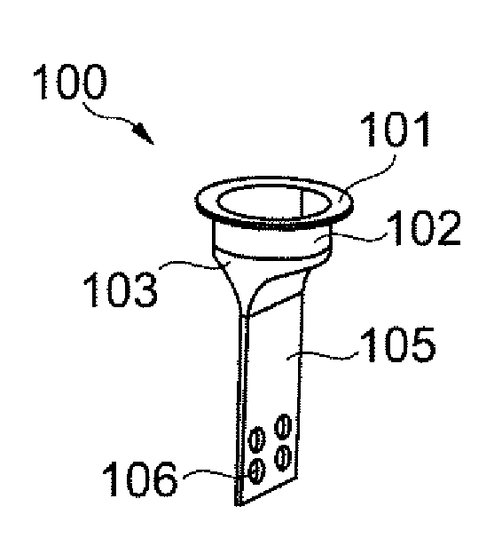
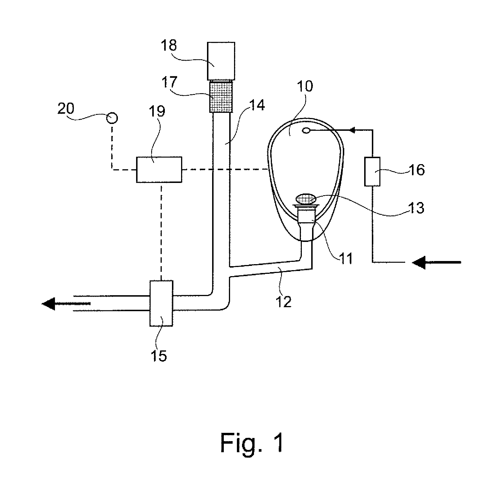
[0025]FIG. 1 shows a vacuum toilet system for an aircraft, according to an exemplary embodiment of the invention. The toilet system comprises a urinal bowl 10 with a drainage device 11 that is connected to a urinal bowl drain line 12. The drainage device 11 contains the odour seal, which will be explained later, as well as a sieve 13. The sieve 13 is placed on the entry end of the odour seal or upstream of the odour seal. The urinal bowl drain line 12 opens into a bypass line 14, which by way of a suction removal valve 15 is connectable to a vacuum system (not shown). In this arrangement the urinal bowl drain line 12 opens upstream of the suction removal valve 15 into the bypass line 14. A flushing-water supply comprising a flushing valve 16 can be provided, which flushing-water supply during flushing action feeds flushing water into the urinal bowl 10. Upstream of the entry of the urinal bowl drain line 12 into the bypass line 14 a bypass odour stopper 17 is provided. It shall prev...


PUM


Abstract

The invention relates to an odor seal for a vacuum toilet drain system whose cross section in the state of no throughflow tapers off in such a way in the downstream direction that the interior walls on the downstream end of the odor seal rest against each other so that the odor seal in a downstream direction allows throughflow while in the opposite direction it blocks throughflow, wherein the downstream end of the odor seal is closed in the state of throughflow and no throughflow of the odor seal. Furthermore, the invention relates to a drainage device comprising such an odor seal and a sieve which is arranged upstream of the odor seal. Moreover, the invention relates to a vacuum toilet system for an aircraft, comprising such an odor seal or a drainage device.

Description

CROSS-REFERENCE TO RELATED APPLICATIONS[0001]This application claims the benefit of the filing date of U.S. Provisional Patent Application No. 61 / 155,985 filed Feb. 27, 2009, the entire disclosure of which application is hereby incorporated herein by reference.FIELD OF THE INVENTION[0002]The invention relates to an odour seal for a vacuum toilet drain system as well as to a drainage device, a vacuum toilet system for an aircraft, and an aircraft comprising such an odour seal.BACKGROUND OF THE INVENTION[0003]In known flushing devices for a vacuum toilet with, for example, a urinal, after use of the urinal, first a flushing liquid is supplied to the urinal, and subsequently a suction removal valve is opened in order to transport urine, flushing liquid and other impurities into the region of a waste water tank. Often a closing valve is provided in the waste water line in order to control the suction removal process or to acoustically seal the waste water system off from the vacuum syst...

Claims


Application Information

Patent Timeline
Patent Type & Authority Patents(United States)
IPC IPC(8): E03D11/00B64D11/00F16K15/14E03D11/18B64C1/00
CPCE03F1/006E03C1/298Y02T50/46B64D11/02Y10T137/7884Y02T50/40
Inventor SEIBT, CHRISTIANHILSE, PETER
Owner AIRBUS OPERATIONS GMBH
Why Eureka
Try Eureka