Vibration-damping device

a technology of vibration control and a single state, which is applied in the direction of spring/damper functional characteristics, shock absorbers, jet propulsion mounting, etc., can solve the problems of reducing the rigidity of the tubular outer member in a single state, affecting the effect of vibration control, and reducing the rigidity of the tubular outer member. , to achieve the effect of preventing deformation reducing the rigidity of the tubular outer member in a singl

Active Publication Date: 2019-06-27
SUMITOMO RIKO CO LTD +1
View PDF0 Cites 2 Cited by
  • Summary
  • Abstract
  • Description
  • Claims
  • Application Information

AI Technical Summary

Benefits of technology

[0038]According to the thirteenth mode, the bracket is secured press-fit in relation to the second mounting member, so that, via the reinforcement effect for the second mounting member, further reinforcement effect for the tubular outer member can be realized by the bracket. In this invention, the tubular outer member and the bracket may be secured press-fit either into or externally about the second mounting member.
[0039]According to this invention, the tubular outer member of the dynamic damper is secured press-fit in relation to the second mounting member and thus reinforced by the second mounting member. This makes it possible to make the deformation rigidity of the tubular outer member in a single state comparatively small, while largely getting the deformation rigidity of the tubular outer member in a mounted state to the second mounting member. Hence, for example, it is possible as well to lighten the tubular outer member by thinning it, while preventing deformation of the tubular outer member. Moreover, the dynamic damper has a structure wherein the mass member is disposed within the tubular outer member and elastically supported at the outer peripheral part thereof by the support rubber. Therefore, prizing displacement of the mass member or the like is less likely to occur in relation to an axial vibration input, so that vibration-control action with respect to the input vibration can be efficiently gotten.

Problems solved by technology

However, as FIGS. 1 and 2 of JP-A-H6-094068 show, if the mass member of the dynamic damper is elastically supported by the rubber on only one side, the rubber easily undergoes elastic deformation with swinging motion upon input of a vibration, which may lead to deterioration of the vibration-control effect by displacement of the mass member.
This may lead to limitation about the forming material of the casing, weight increase by thickening of the casing, or the like.

Method used


Image

  • Vibration-damping device
  • Vibration-damping device
  • Vibration-damping device

Examples


Embodiment Construction

[0050]Embodiments of the present invention will be described below in reference to the drawings.

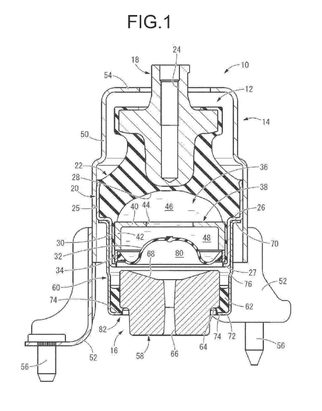
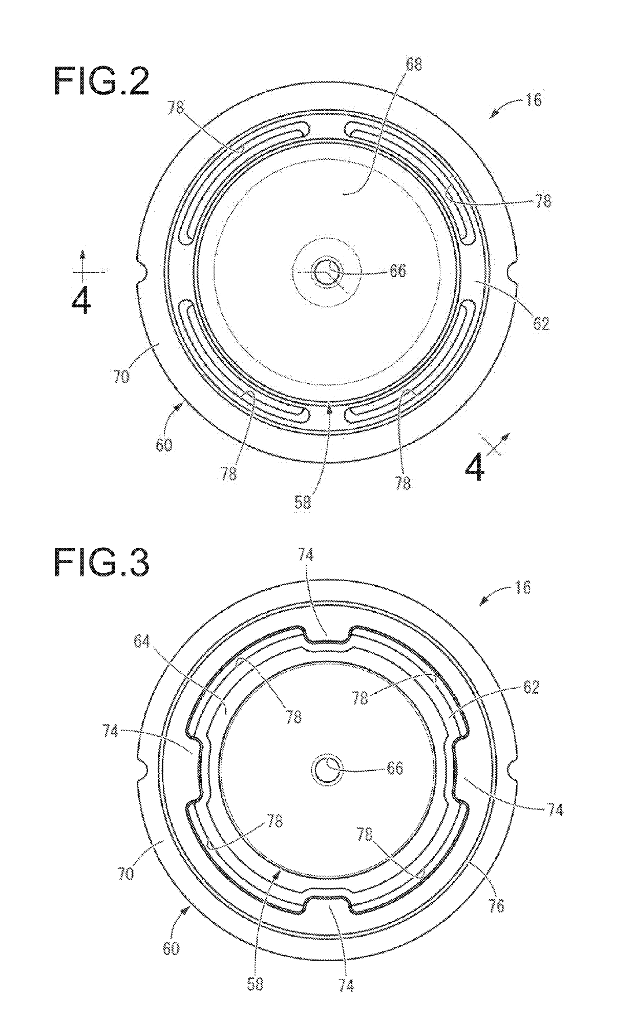
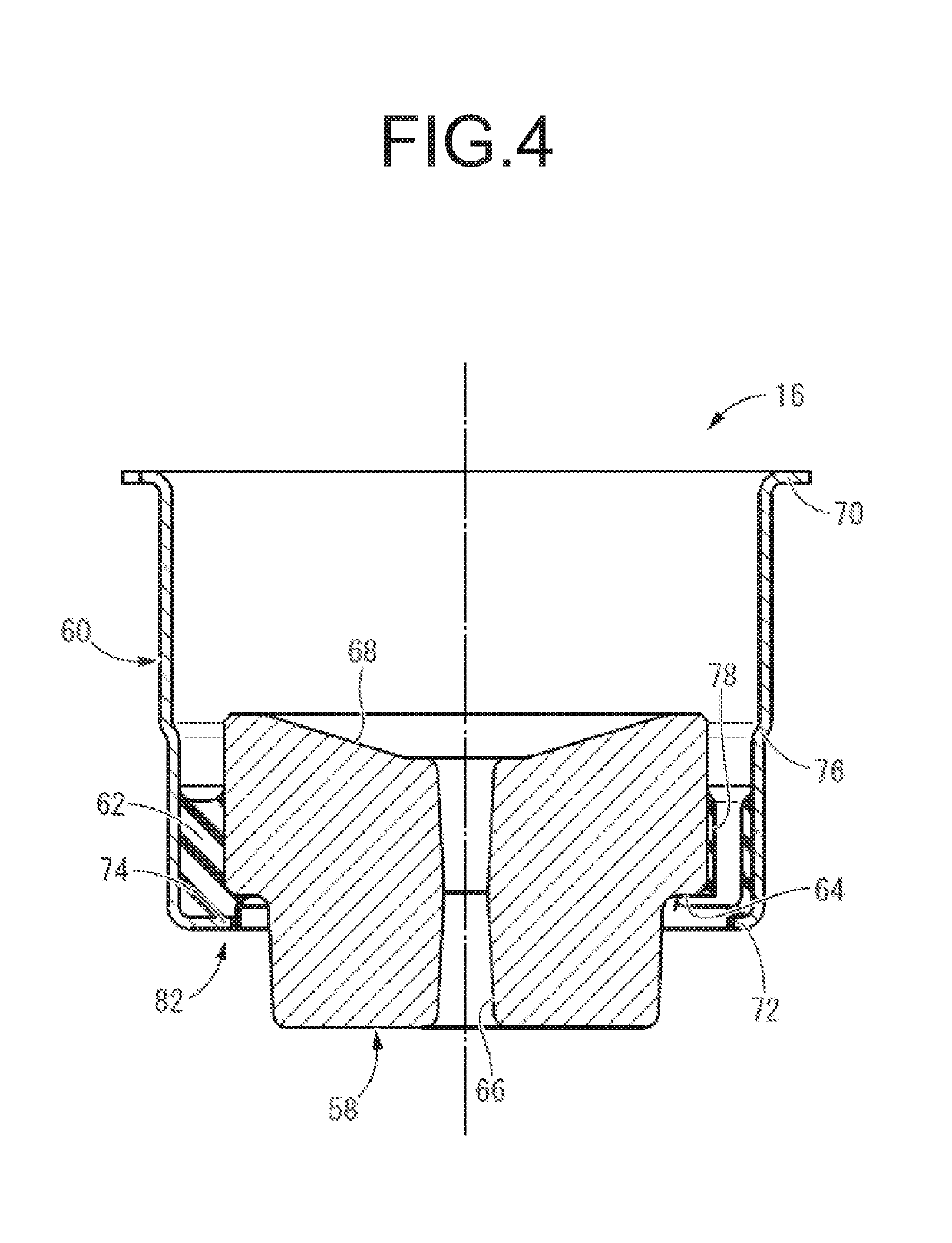
[0051]FIG. 1 shows an automotive engine mount 10 as a first embodiment of a vibration-damping device having a structure according to this invention. The engine mount 10 has a structure wherein a bracket 14 and a dynamic damper 16 are attached to a mount main body 12. In description hereinafter, the up-down direction is the axial direction and the up-down direction in FIG. 1, which is substantially the vertical up-down direction in a state of being mounted on the vehicle described later.

[0052]More specifically, the mount main body 12 is a fluid-filled vibration-damping device having a structure wherein a first mounting member 18 and a second mounting member 20 are elastically connected to each other by a main rubber elastic body 22.

[0053]The first mounting member 18 is a high rigidity member made of metal or the like in a roughly cylindrical shape extending in the axial direction as a whol...


PUM

PropertyMeasurementUnit
viscosityaaaaaaaaaa
elasticaaaaaaaaaa
flexibleaaaaaaaaaa

Abstract

A vibration-damping device including: a first mounting member configured to be mounted to one of components of a vibration transmission system; a second mounting member configured to be mounted to an other of the components of the vibration transmission system; a main rubber elastic body connecting the first mounting member and the second mounting member elastically to each other; a bracket attached to the second mounting member, the bracket having a mounting part configured to be mounted to the other of the components of the vibration transmission system; a tubular outer member secured press-fit to the second mounting member; a mass member disposed within the tubular outer member; and a support rubber fixed at an outer peripheral part of the mass member, the support rubber elastically connecting the tubular outer member and the mass member to constitute a dynamic damper.

Description

INCORPORATED BY REFERENCE[0001]The disclosures of Japanese Patent Application Nos. 2017-246569 filed on Dec. 22, 2017 and 2018-098880 filed on May 23, 2018, each including the specification, drawings and abstract is incorporated herein by reference in its entirety.BACKGROUND OF THE INVENTION1. Field of the Invention[0002]The present invention relates to a vibration-damping device that is applied to an automotive engine mount, etc., and especially relates to a vibration-damping device including a dynamic damper.2. Description of the Related Art[0003]Conventionally, there has been known a vibration-damping device that is applied to an automotive engine mount, etc. The vibration-damping device has a structure wherein a first mounting member and a second mounting member, each being mounted to either one of components of a vibration transmission system, are elastically connected by a main rubber elastic body.[0004]For example, in Japanese Unexamined Patent Publication No. JP-A-H6-094068,...

Claims


Application Information

Patent Timeline
Patent Type & Authority Applications(United States)
IPC IPC(8): B60K5/12F16F13/04F16F15/02
CPCB60K5/1283F16F13/04B60K5/1208F16F15/022F16F2224/025F16F2230/0005F16F2228/04F16F13/22
Inventor YASUDA, TAKAYOSHIWATANABE, YOSHINORIFURUMACHI, NAOKIHATANAKA, KEISHIICHIKAWA, HIROYUKIMATSUBARA, YUJIMORI, KENTARO
Owner SUMITOMO RIKO CO LTD
Why Eureka
Try Eureka