Orthopedic implant having non-circular cross section and method of use thereof

a non-circular, implant technology, applied in the field of orthopedic implants, can solve the problems of providing rotational stabilization, inferior holding capacity, soft and spongy material, etc., and achieve the effect of promoting joint fusion, eliminating or minimizing, and effective immobilizing the join

Inactive Publication Date: 2014-08-07
GREENBERG LOUIS E +3
View PDF51 Cites 7 Cited by
  • Summary
  • Abstract
  • Description
  • Claims
  • Application Information

AI Technical Summary

Benefits of technology

[0013]Benefits and advantages of embodiments of the present invention include, but are not limited to, providing an orthopedic implant: (1) capable of compressing adjacent bones along a fracture line or a joint therebetween using external portions of these bones with no reliance on the soft, spongy materials interior thereto; (2) effective for promoting joint fusion without requiring the bony surfaces on both sides of the joint to be surgically abraded and compressed with bone screws and, as anticipated by the present inventors, without requiring lengthy healing periods; (3) effective for immobilizing the joint, thereby eliminating or minimizing the need for supplemental casting of the joint or use of other immobilization hardware during healing, which is important for veterinary applications where casting may be difficult; and (4) effective for stabilizing the bones during the bony ingrowth healing phase.

Problems solved by technology

As stated, bone fixation / fusion systems, with the exception of cable-type orthopedic implants, which cannot provide rotational stabilization, are generally anchored to the cancellous bone material in the interior of the bone.
This material is soft and spongy and has inferior holding capability when compared to the exterior, cortical bone portions.
The forces imposed on such devices may exceed the holding capability of the cancellous bone, and may result in implant failure.

Method used


Image

  • Orthopedic implant having non-circular cross section and method of use thereof
  • Orthopedic implant having non-circular cross section and method of use thereof
  • Orthopedic implant having non-circular cross section and method of use thereof

Examples


Embodiment Construction

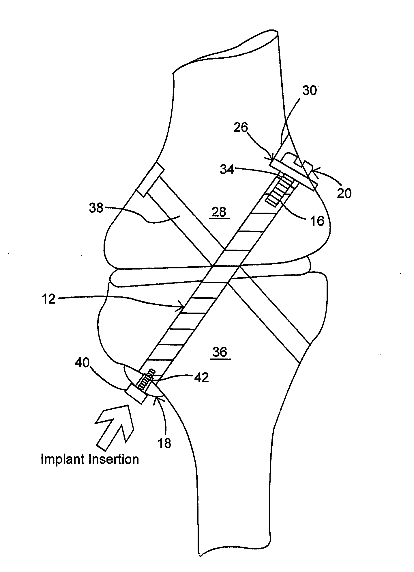
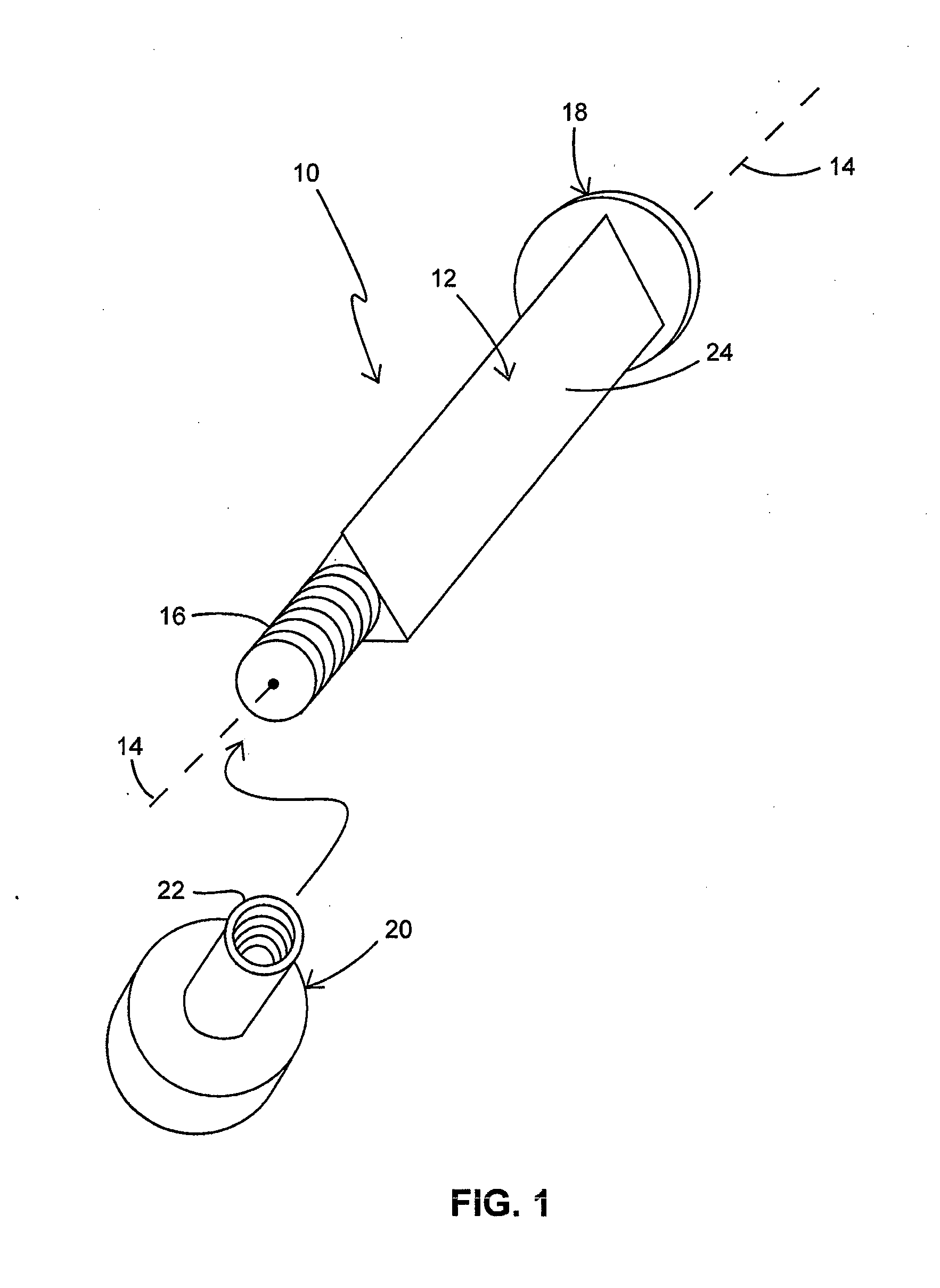
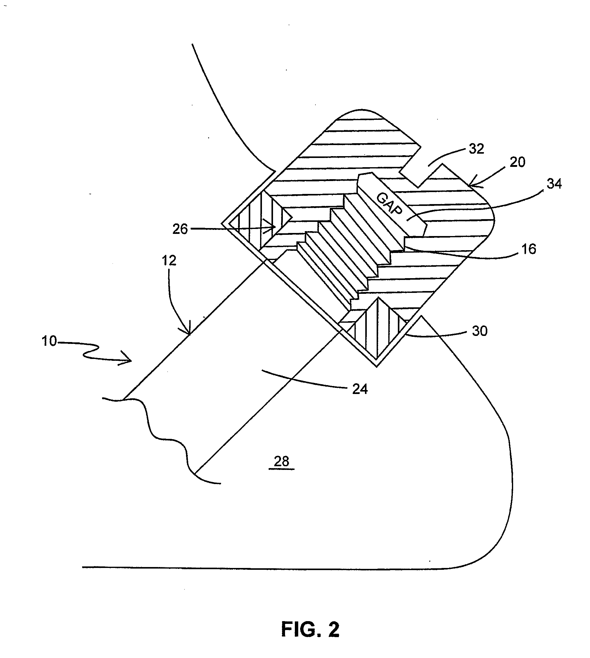
[0020]Briefly, embodiments of the present invention include titanium orthopedic implants, coated to encourage bony in-growth or through-growth, for the fusion, management and repair of bone joints and bone fractures. Examples of applications of such implants are femoral stems for total hip replacements, surfaces on the tibial and femoral sides of total knee implants and surfaces on the tibial and talar sides of total ankle implants. One embodiment of such implants includes an elongated shaft coated to encourage bony in-growth, having a non-round cross section (triangular, as an example), and a flange at one end (the proximal end), which is laterally inserted into a preformed insertion path formed in adjacent bone segments traversing a joint or fracture location, to the point where further insertion is blocked by the flange intersecting one of the bone segments. The other end of the shaft (the distal end) may have a portion of male thread protruding out of the insertion path in the s...


PUM


Abstract

Orthopedic implants capable of compressing adjacent bone segments into which they are inserted, effective for the fusion, management and repair of bone joints and bone fractures, and methods for their installation, are described. One embodiment of such implants includes an elongated shaft coated to encourage bony in-growth, having a non-round cross section, and a flange at one end, which is laterally inserted into a preformed insertion path formed in adjacent bone segments traversing a joint or fracture location, to the point where further insertion is blocked by the flange intersecting one of the bone segments. The other end of the shaft may have a portion of male thread protruding out of the insertion path in the second of the bone fragments and adapted to be mated to a fastener having female thread. When the fastener is tightened against the outside of the second bone segment, perhaps using a washer, the joint or fracture is compressed and stabilized resulting in an effective fusion of the joint or fracture when the bone secures itself in the insertion path to the shaft's bony in-growth surfaces on both sides of the joint or fracture line.

Description

CROSS-REFERENCE TO RELATED APPLICATIONS[0001]The present application claims the benefit of U.S. Provisional Patent Application No. 61 / 725,580 for “Orthopedic Implant Having Non-Circular Cross Section And Method Of Use Thereof,” which was filed on Nov. 13, 2012, the entire content of which is hereby specifically incorporated by reference herein for all that it discloses and teaches.FIELD OF THE INVENTION[0002]The present invention relates generally to orthopedic devices for fixation or fusion of bones and, more particularly, to the use of bony in-growth or through-growth coated orthopedic implants for securing bone segments against one another, for example, for fixing bone fractures or for fusing bones.BACKGROUND OF THE INVENTION[0003]There are numerous bone fixation / fusion systems, devices and associated methods for stabilizing adjacent bone segments, thereby enhancing the healing of fractures and / or promoting union of joints being fused together. Adjacent bone segments may include ...

Claims


Application Information

Patent Timeline
Patent Type & Authority Applications(United States)
IPC IPC(8): A61B17/86
CPCA61B17/86A61B2017/00831A61B2017/564A61B17/8695A61B17/683
Inventor GREENBERG, LOUIS E.MCABEE, KEVIN P.CAILE, WILLIAM C.WHITE, JACKSON L.
Owner GREENBERG LOUIS E
Why Eureka
Try Eureka