
Laundry treatment apparatus

a technology for washing machines and laundry, applied in the field of laundry treatment apparatuses, can solve the problems of unbalance, unintentional rotation of the drum, and failure of dynamic balance with regard to the aforementioned laundry treatment apparatus

Active Publication Date: 2014-08-14
LG ELECTRONICS INC
View PDF4 Cites 30 Cited by
  • Summary
  • Abstract
  • Description
  • Claims
  • Application Information

AI Technical Summary

Benefits of technology

The present invention is related to a laundry treatment apparatus that can actively eliminate dissymmetric rotation (unbalance) of the drum where the laundry is stored. This is achieved by supplying liquid into the device that agitates the laundry to reduce the unbalance. The apparatus can also eliminate unbalance in both the plane parallel to the drum's diameter direction and the plane parallel to the drum's longitudinal direction. The apparatus includes a guide that directs the liquid from the feeder into the first flow path body and prevents the liquid from moving in the opposite direction of the drum's rotation. The guide is designed to temporarily prevent the liquid from moving in the drum's rotation direction or in a opposite direction. Overall, this invention improves the efficiency of the laundry treatment process by reducing unbalance and promoting improved load control.

Problems solved by technology

The drum may fail to maintain dynamic balance because of the position of laundry stored therein, which may cause unintentional rotation of the drum.
On the other hand, failure of dynamic balance (i.e. unbalance) with regard to the aforementioned laundry treatment apparatus refers to a state in which the mass distribution about a rotation axis of the drum is not constant during rotation of the drum.
This unbalance occurs when laundry is not uniformly distributed within the drum.
Rotation of the unbalanced drum causes vibration, and in turn noise is generated as vibration of the drum is transmitted to a tub or a cabinet.
Although the above described unbalance control method is available in a steady state in which vibration of the drum falls within a given range, it is impossible to anticipate the large effects of a transient state (i.e., in a transient vibration state) before vibration of the drum reaches the steady state.
Additionally, conventional balancing units have difficulty in actively eliminating unbalance as soon as unbalance occurs.

Method used


Image

  • Laundry treatment apparatus
  • Laundry treatment apparatus
  • Laundry treatment apparatus

Examples


Embodiment Construction

[0058]Hereinafter, exemplarily embodiments of the present invention will be described in detail with reference to the accompanying drawings. A configuration of an apparatus that will be described hereinafter and a control method of the apparatus are provided for explanation of the exemplarily embodiments of the present invention and are not intended to limit the technical scope of the present invention. The same reference numerals of the entire specification designate the same constituent elements.

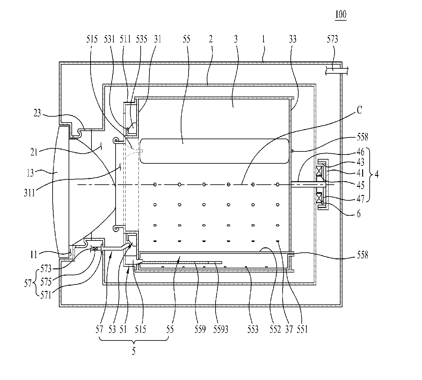
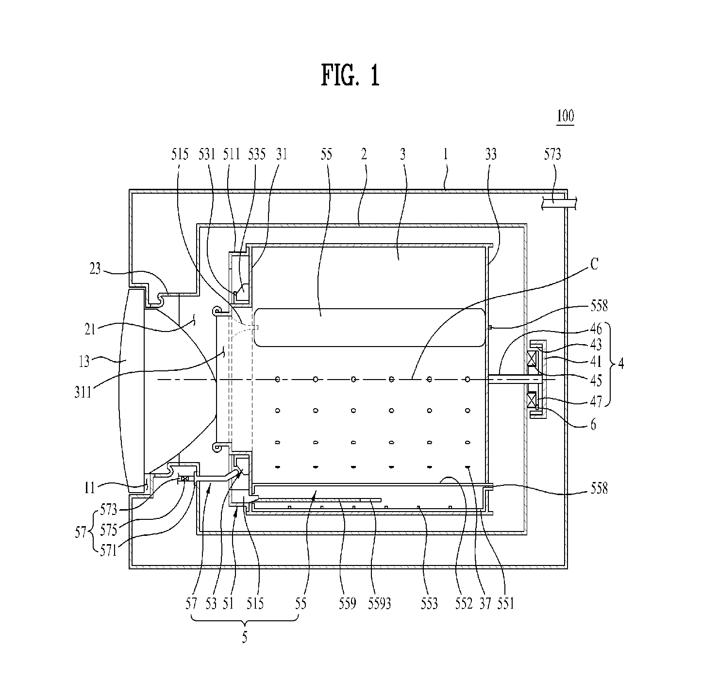
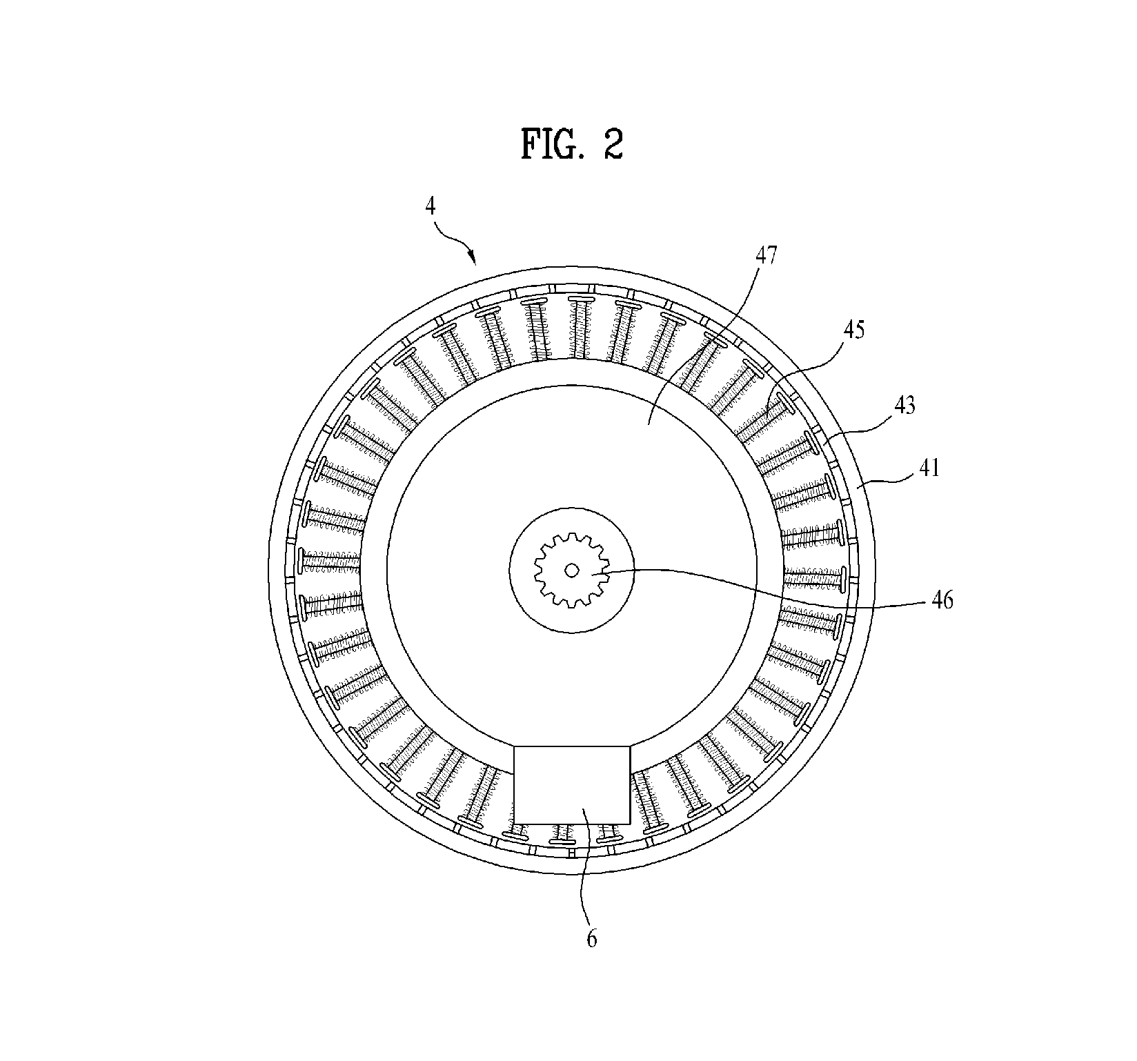
[0059]As exemplarily shown in FIG. 1, a laundry treatment apparatus of one embodiment of the present invention, designated by reference numeral 100, includes a cabinet 1 defining an external appearance of the apparatus 100, a tub 2 placed within the cabinet 1 and configured to store wash water therein, a drum 3 rotatably placed within the tub 2 and configured to store laundry therein, a drive unit 4 to rotate the drum 3, and a balancing unit 5 to control unbalance of the drum 3 by increasi...


PUM


Abstract

A laundry treatment apparatus including a rotatable drum in which laundry is stored, at least three balancers mounted to the drum so as to be spaced apart from one another by the same angle around a rotation center of the drum. Liquid is introduced into and discharged from the balancers via a feeder supplying the liquid and a flow path structure mounted to the drum to guide liquid supplied from the feeder to the balancer located in a direction for removal of unbalance of the drum.

Description

[0001]Pursuant to 35 U.S.C. §119(a), this application claims the benefit of Korean Patent Application No. 10-2013-0015375, filed on Feb. 13, 2013, which is hereby incorporated by reference as if fully set forth herein.BACKGROUND[0002]1. Field[0003]The present disclosure relates to a laundry treatment apparatus.[0004]2. Discussion of the Related Art[0005]A conventional laundry treatment apparatus includes a cabinet defining an external appearance of the apparatus, a tub installed within the cabinet, a drum rotatably installed within the tub such that laundry is washed in the drum, and a motor. The motor includes a rotating shaft which penetrates the tub and is coupled to the drum to rotate the drum.[0006]The drum may fail to maintain dynamic balance because of the position of laundry stored therein, which may cause unintentional rotation of the drum.[0007]Dynamic balance refers to a state of a rotating rotator in which centrifugal force or moment of centrifugal force becomes zero wit...

Claims


Application Information

Patent Timeline
IPC IPC(8): D06F37/22D06F37/20D06F33/48
CPCD06F37/225D06F37/203D06F37/06D06F39/088D06F37/04D06F2105/02D06F33/48D06F2103/26F16F15/32D06F37/22
Inventor KIM, KEUNJOOPARK, SEUNGCHULKIM, JONGRYONG
Owner LG ELECTRONICS INC
Learn More