Micro-electromechanical gyro device

Inactive Publication Date: 2014-08-14
TRONICS MICROSYST
View PDF2 Cites 22 Cited by
  • Summary
  • Abstract
  • Description
  • Claims
  • Application Information

AI Technical Summary

Benefits of technology

[0029]further electrical requirements, references and converters
[0033]b) determining an additional output signal Syout by differential detection of said additional signals on the basis of the following formula:
[0038]The compensation factor p is the same for both out

Problems solved by technology

The problem of this structure is that there is a net reaction force acting on the base plate during the swing

Method used


Image

  • Micro-electromechanical gyro device
  • Micro-electromechanical gyro device
  • Micro-electromechanical gyro device

Examples


Embodiment Construction

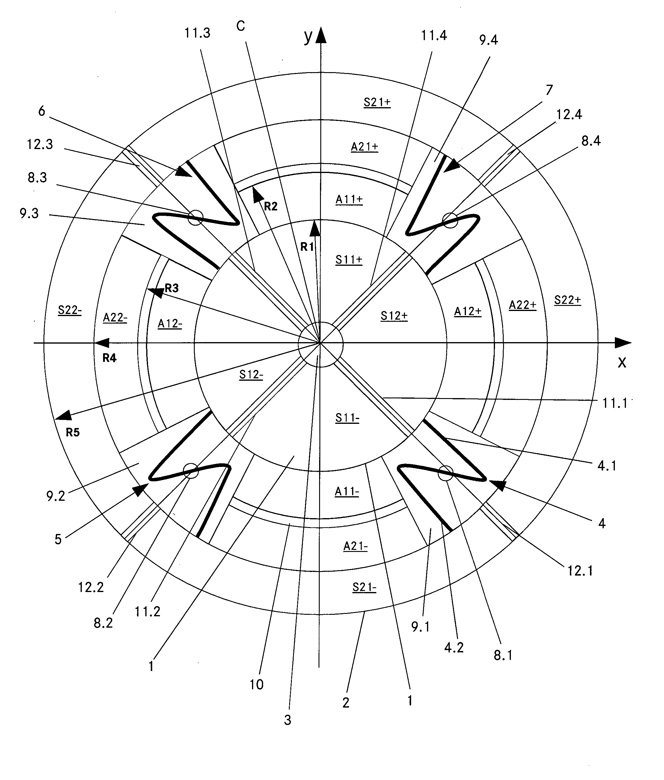
[0087]FIG. 1 illustrates a preferred embodiment of the invention. There is a first mobile mass 1 and a second mobile mass 2. The first mass 1 is substantially a circular disk. In the present embodiment the disk has an opening 3 in the center. The radius R1 of the circular disk may be in the range of 0.1 mm to 3 mm. The second mass 2 is ring-shaped and surrounds the first mass 1. The inner radius R4 of the second mass 2 may be in the range of 0.12 mm to 4 mm and the outer radius R5 may be about 0.2 mm to 6 mm. The second mass 2 completely surrounds the first mass 1.

[0088]The two masses are mechanically connected by four Z-shaped coupling elements 4, 5, 6, 7. All of them are identical. The following description, therefore, only refers to the coupling element 4.

[0089]The coupling element 4 is supported on a post 8.1 (anchor point) of the substrate. The post 8.1 acts as a dot-like anchor for the coupling element 4. It supports the coupling element 4 at a certain distance above the subst...


PUM


Abstract

A resonator micro-electronic gyro, preferably a micro-electromechanical system (MEMS) gym comprises a first and a second resonator mass (1, 2) suspended for rotational vibration. The two masses (1, 2) are flexibly connected by four mechanical coupling elements (4, 5, 6, 7) for anti-phase vibration. There is at least one positive and at least one negative sensing electrode (S11+, S11−, S21+, S21−) on each resonator mass (1, 2) for detecting an out-of-plane output movement of the masses (1, 2). A detection circuit is connected to be said positive and negative sensing electrodes and determines the output signal by differential detection of the signals on the basis of the following formula: Sxout=({S21+}−M{S11+})−({S21−}−M{S11−}), wherein {S21+}, {S21−} sensing electrode signals of the positive and negative detection electrode of the second mass, respectively; {S11+}, {S11−} sensing electrode signals of the positive and negative detection electrode of the first mass, respectively, μ=compensation factor.

Description

TECHNICAL FIELD [0001]The invention relates to a method for detecting an output signal of a resonator micro-electronic gyro preferably of a micro-electromechanical system (MEMS) gyro comprising the steps of:[0002]a) activating a vibrational in-plane movement of a first and a second resonator mass suspended for rotational vibration, and[0003]b) providing an anti-phase vibration of the first and second vibrating mass by at least one mechanical coupling element flexibly connecting the first and the second resonator mass for anti-phase vibration.[0004]The invention also relates to a resonator micro-electronic gyro comprising:[0005]a) a first and a second resonator mass suspended for rotational vibration,[0006]b) at least one mechanical coupling element flexibly connecting the first and the second resonator mass for anti-phase vibration,[0007]c) at least one positive and at least one negative sensing electrode on each resonator mass for detecting an out-of-plane output movement of the ma...

Claims


Application Information

Patent Timeline
IPC IPC(8): G01C19/5712
CPCG01C19/5712
Inventor LECLERC, JACQUES
Owner TRONICS MICROSYST
Why Eureka
Try Eureka