

Pneumatic tire
a technology of pneumatic tires and cylinders, which is applied in the direction of non-skid devices, vehicle components, transportation and packaging, etc., can solve the problems of increasing the collapse of the block upon ground contact, the rigidity of the block in the circumferential direction of the tire, and the inability to achieve an improvement in the shear force of the snow column, so as to improve the on-snow performance, increase the on-snow braking performance and the on-snow traction performance performance, and increase the on-snow performan
Active Publication Date: 2014-08-14
BRIDGESTONE CORP
View PDF5 Cites 11 Cited by
- Summary
- Abstract
- Description
- Claims
- Application Information
AI Technical Summary
Benefits of technology
The invention is a pneumatic tire designed to improve its performance on snowy roads. It achieves this by simultaneously improving its ground contact area (the part in contact with the road surface), increasing its scratch effect on the road surface, and enhancing its snow column shear force. This results in improved friction characteristics and better performance on braking, traction, and turning. The tire has cutaway grooves and a connecting narrow groove that intersect with each other, which improves the snow column shear force and maintains the flexural rigidity of the tire to a high level.
Problems solved by technology
In a conventional pneumatic tire, however, in which a plurality of main grooves extending along the tire circumferential direction and a plurality of lateral grooves extending along the tire width direction are formed on the tread surface to define rectangular blocks, with sipes formed in the blocks, it has not been possible to achieve an improvement in snow column shear force, a guarantee of tire ground contact area, and an improvement in the scratch effect on the road surface simultaneously.
In other words, in the above conventional pneumatic tire, upon increasing the groove depth of the lateral grooves in order to enhance the snow column shear force, the rigidity of the block in the tire circumferential direction decreases, and the angle of collapse of the block upon ground contact ends up increasing, thus making it impossible to guarantee the tire ground contact area.
Furthermore, if the number of grooves or sipes formed in the tread surface is increased in order to enhance the scratch effect on the road surface due to edges of blocks and edges of sipes, the rigidity of the block decreases, and the angle of collapse of the block upon ground contact ends up increasing, thus making it impossible to guarantee the tire ground contact area.
On the other hand, in order to guarantee the tire ground contact area by suppressing the decrease in rigidity of the block, it is necessary to form rib-shaped land portions instead of blocks in the tread surface or to suppress the sipe density to be within a predetermined range (for example, see JP2001-71713A (PTL 1)), thus making it impossible to enhance the snow column shear force and the scratch effect on the road surface.
Method used
View moreImage
Smart ImageViewing Examples

Examples
example 1
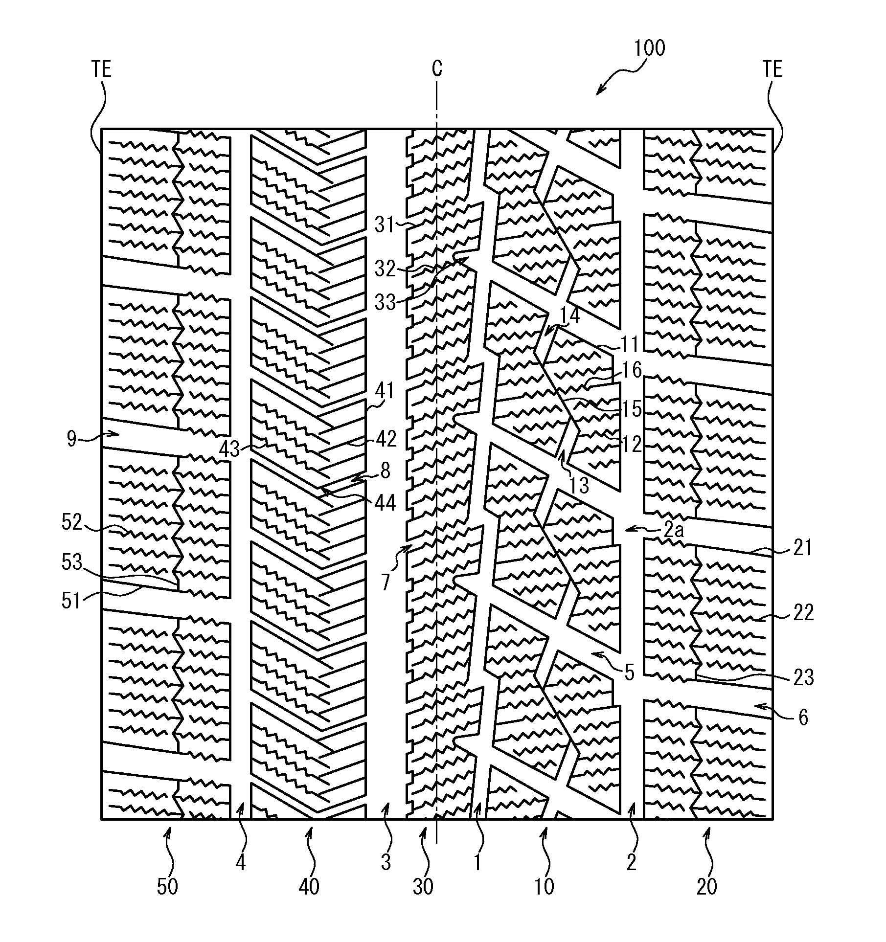
[0103]195 / 65R15 size pneumatic tires having the specifications listed in Table 1 and including the tread surface 100 with the structure shown in FIG. 1 were produced, and performance was evaluated with the method below. Table 1 lists the results.
[0104]Note that the specifications for the lateral grooves listed in Table 1 are the specifications for the lateral grooves 5 defining the blocks 11.
Login to View More PUM
 Abstract
A pneumatic tire according to the present invention includes, one or more main grooves extending in the tire circumferential direction, and a plurality of lateral grooves extending in the tire width direction, the main grooves and the lateral grooves defining a block row formed by a plurality of blocks, at least one sipe being disposed in each block. Each block has a first cutaway groove with one end opening into a lateral groove located on one side of the block and the other end terminating within the block, a second cutaway groove with one end opening into a lateral groove located on the other side of the block and the other end terminating within the block, and a connecting narrow groove having a groove width narrower than that of the first and the second cutaway groove and connecting the first and the second cutaway groove.
Description
TECHNICAL FIELD[0001]The present invention relates to a pneumatic tire, particularly to a pneumatic tire with excellent on-snow performance.BACKGROUND ART[0002]In general, it is desired that pneumatic tires suitable for snowy roads, including roads with compacted snow, have excellent braking performance (on-snow braking performance), traction performance (on-snow traction performance), and turning performance (on-snow turning performance) on snowy roads.[0003]Normally, the braking performance, traction performance, turning performance, and the like of a tire are affected by the friction characteristics of the tire. Therefore, in order to improve the on-snow braking performance, on-snow traction performance, and on-snow turning performance of a tire, it is necessary to improve the friction characteristics of the tire on snowy roads.[0004]One known way of improving the friction characteristics of a tire on snowy roads is to enhance the shear resistance of the snow column formed in a g...
Claims
Login to View More Application Information
Patent Timeline
 Patent Type & AuthorityApplications(United States)
IPC IPC(8): B60C11/03
CPCB60C2011/0339B60C11/0306B60C11/0304B60C2011/1213B60C2011/0341B60C2011/0369B60C11/1369B60C2011/0388B60C2011/1209B60C11/1236B60C2011/0381
InventorOCHI, NAOYAHASHIMOTO, KENTO
OwnerBRIDGESTONE CORP