Magnet embedded rotor and method of manufacturing the magnet embedded rotor

a technology of magnetic embedded rotors and manufacturing methods, which is applied in the direction of magnetic body, magnetic circuit rotating parts, magnetic circuit shapes/forms/construction, etc., can solve the problems of reduced effective magnetic flux interlinking with the stator coil of the motor, difficult to supply a sufficient amount of magnetic flux to the magnetic body, and difficult to achieve the effect of improving the magnetic effect ratio of field permanent magnets

Inactive Publication Date: 2014-08-14
JTEKT CORP
View PDF14 Cites 6 Cited by
  • Summary
  • Abstract
  • Description
  • Claims
  • Application Information

AI Technical Summary

Benefits of technology

[0010]One object of the invention is to provide a magnet embedded rotor configured such that the magnetization ratio of field permanent magnets is improved, and a method of manufacturing the magnet embedded rotor.

Problems solved by technology

Therefore, if the area of the outer peripheral face of the rotor is small relative to the area of the surfaces of the magnetic bodies to be magnetized, it is difficult to supply a sufficient amount of magnetic flux to the magnetic bodies.
Therefore, when the magnetic bodies are embedded in a radially inside portion of the rotor, it is difficult to supply a sufficient amount of magnetic flux to the magnetic bodies.
This leads to a reduction in the amount of effective magnetic flux interlinking with a stator coil of a motor, and constitutes a factor causing a decrease in the motor output torque.

Method used


Image

  • Magnet embedded rotor and method of manufacturing the magnet embedded rotor
  • Magnet embedded rotor and method of manufacturing the magnet embedded rotor
  • Magnet embedded rotor and method of manufacturing the magnet embedded rotor

Examples


Embodiment Construction

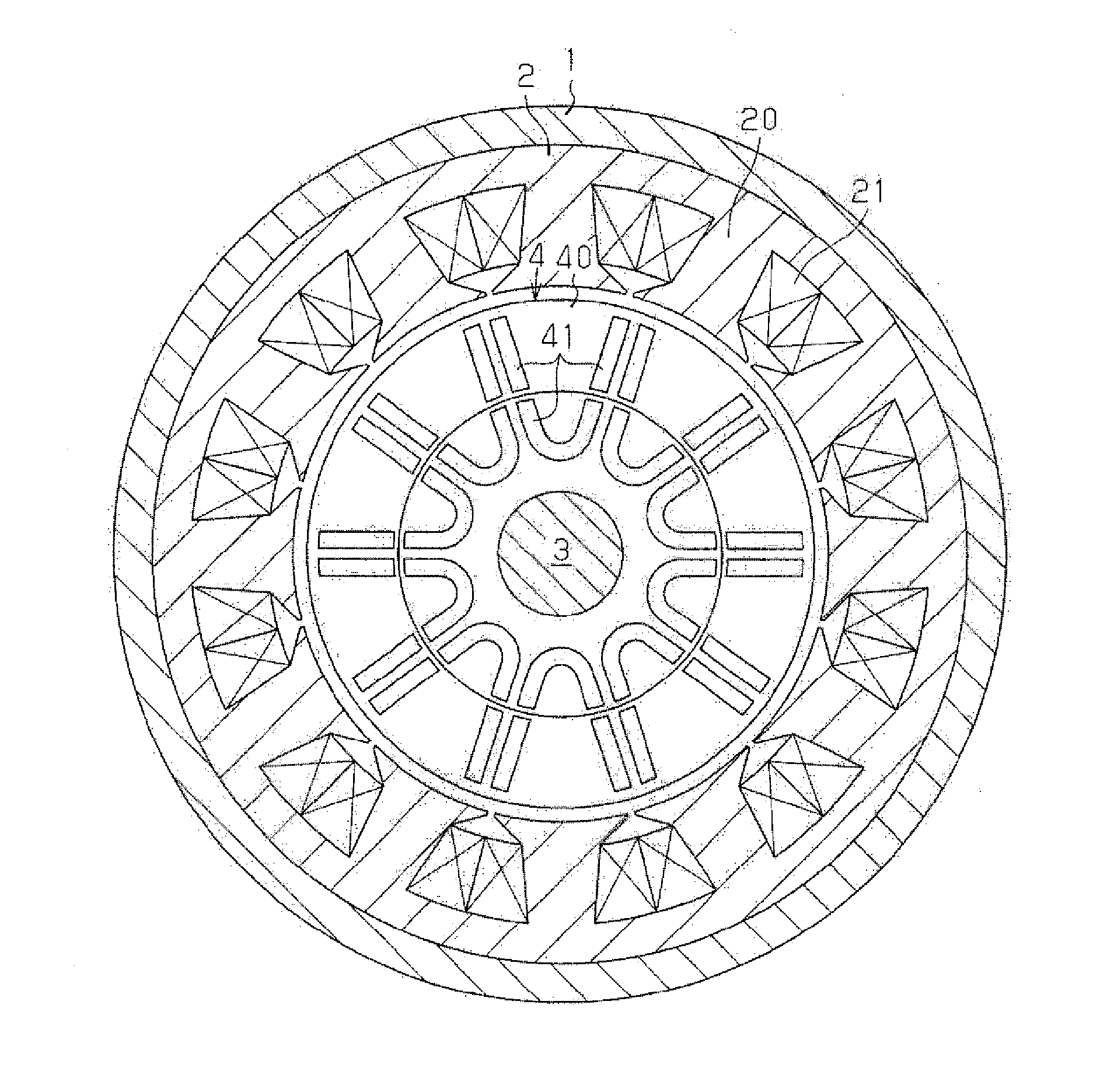
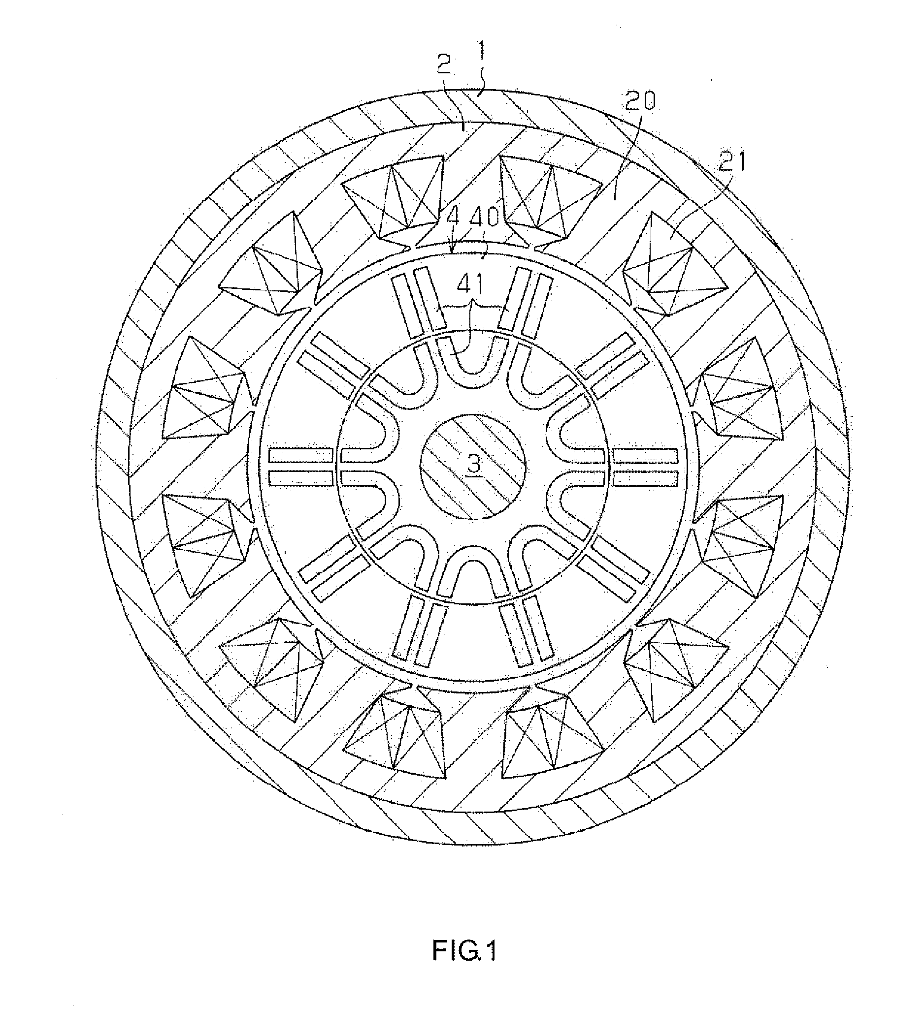
[0022]Hereinafter, a magnet embedded rotor according to an embodiment of the invention will be described. First, the structure of an IPM motor including the magnet embedded rotor according to the present embodiment will be described with reference to FIG. 1. As illustrated in FIG. 1, the IPM motor includes a cylindrical stator 2 fixed to the inner peripheral face of a housing 1, an output shaft 3 rotatably supported by the housing 1 via bearings (not illustrated), and a rotor 4 fixedly fitted to the outer periphery of the output shaft 3.

[0023]The stator 2 has a structure in which multiple magnetic steel plates are laminated in its axial direction. Twelve teeth 20, which extend radially inward, are formed on the inner peripheral face of the stator 2. Stator coils 21 are wound around the respective teeth 20.

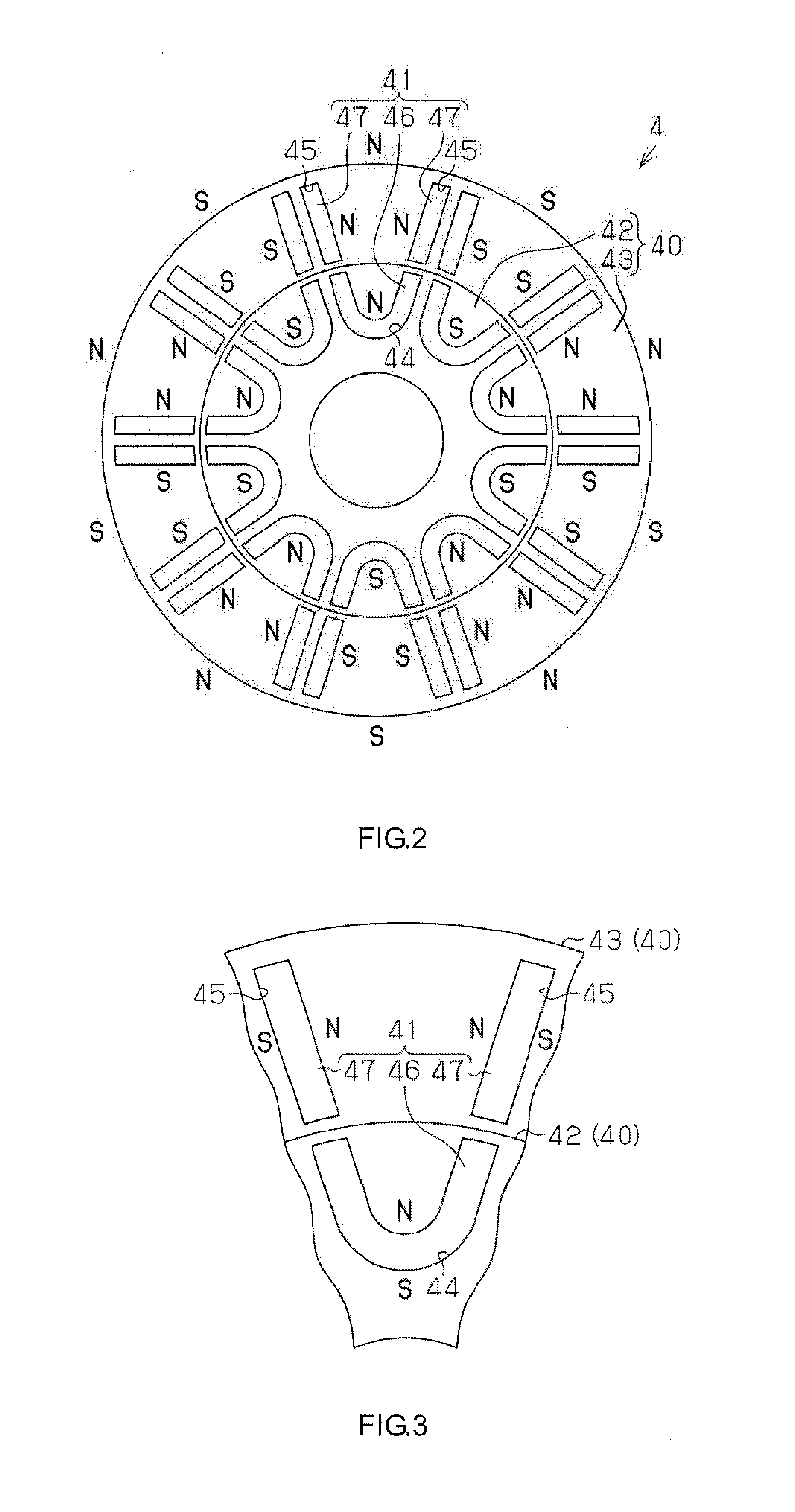
[0024]The rotor 4 includes a cylindrical rotor core 40 and ten sets of U-shaped field permanent magnets 41 embedded in the rotor core 40. As illustrated in FIG. 2, the rotor core 4...


PUM


Abstract

A magnet embedded rotor configured such that the magnetization ratio of field permanent magnets is improved is provided. The magnet embedded rotor includes a first annular core in which first permanent magnets are embedded, and a second annular core in which second permanent magnets, which are independent from the first permanent magnets, are embedded. The magnet embedded rotor has a structure in which the second annular core is fitted onto the outer periphery of the first annular core. The first permanent magnets and the second permanent magnets constitute field permanent magnets.

Description

INCORPORATION BY REFERENCE[0001]The disclosure of Japanese Patent Application No. 2013-025769 filed on Feb. 13, 2013 including the specification, drawings and abstract is incorporated herein by reference in its entirety.BACKGROUND OF THE INVENTION[0002]1. Field of the Invention[0003]The invention relates to a magnet embedded rotor and a method of manufacturing the magnet embedded rotor.[0004]2. Description of the Related Art[0005]There has been known an interior permanent magnet motor (IPM motor) having a structure in which field permanent magnets are embedded in a rotor. As a method of manufacturing a magnet embedded rotor used in such an IPM motor, a method described in Japanese Patent Application Publication No. 2010-193587 (JP 2010-193587 A) has been known. In this method, a cylindrical rotor having a plurality of magnet insertion holes is prepared, magnetic bodies are embedded in the magnet insertion holes, and then a magnetizing device is arranged so as to cover the outer peri...

Claims


Application Information

Patent Timeline
Patent Type & Authority Applications(United States)
IPC IPC(8): H02K1/27
CPCH02K1/274H01F13/003H02K1/2773H02K15/03H02K2201/15
Inventor YOSHIKAWA, HIROSHIHIRAMITSU, AKIRA
Owner JTEKT CORP
Why Eureka
Try Eureka