Motion video predict coding method, motion video predict coding device, motion video predict coding program, motion video predict decoding method, motion predict decoding device, and motion video predict decoding program

a technology of motion video and coding method, applied in the direction of signal generator with optical-mechanical scanning, color television with bandwidth reduction, signal generator, etc., to achieve the effect of improving encoding efficiency

Active Publication Date: 2014-08-14
NTT DOCOMO INC
View PDF1 Cites 6 Cited by
  • Summary
  • Abstract
  • Description
  • Claims
  • Application Information

AI Technical Summary

Benefits of technology

[0004]Using encoding techniques, a picture which is used as an encoding target is divided into a plurality of blocks and then an encoding process and a decoding process are carried out on a block basis. Predictive encoding methods as described below are used in order to improve encoding efficiency. In intra-frame predictive encoding, a predicted signal is generated using a previously-reproduced neighboring picture signal (a reconstructed signal reconstructed from picture data compressed in the past) present in the same frame as a target block, and then a residual signal obta...

Problems solved by technology

Therefore, an example conventional technology may have a problem that the same information has to be r...

Method used


Image

  • Motion video predict coding method, motion video predict coding device, motion video predict coding program, motion video predict decoding method, motion predict decoding device, and motion video predict decoding program
  • Motion video predict coding method, motion video predict coding device, motion video predict coding program, motion video predict decoding method, motion predict decoding device, and motion video predict decoding program
  • Motion video predict coding method, motion video predict coding device, motion video predict coding program, motion video predict decoding method, motion predict decoding device, and motion video predict decoding program

Examples


Embodiment Construction

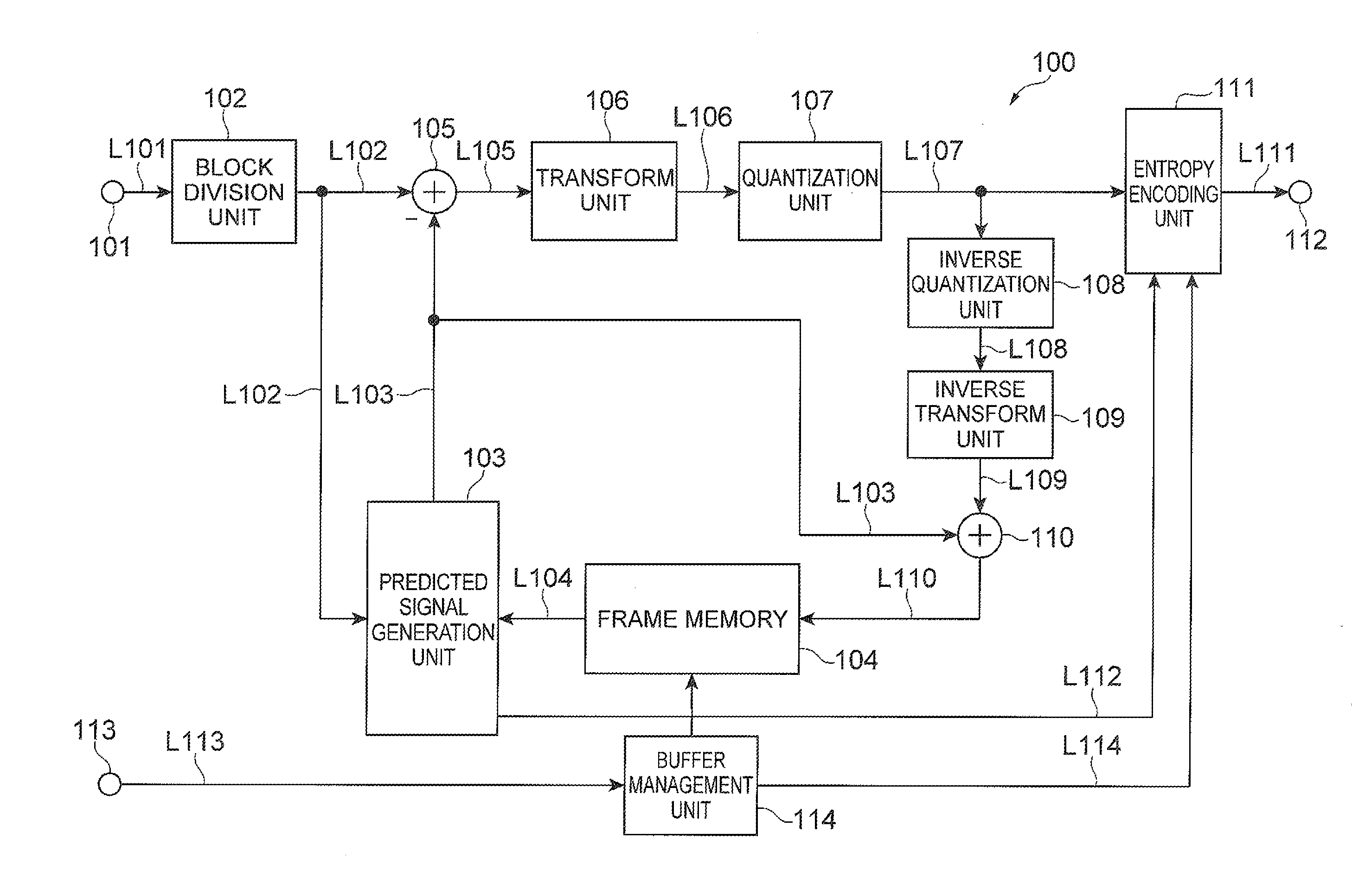
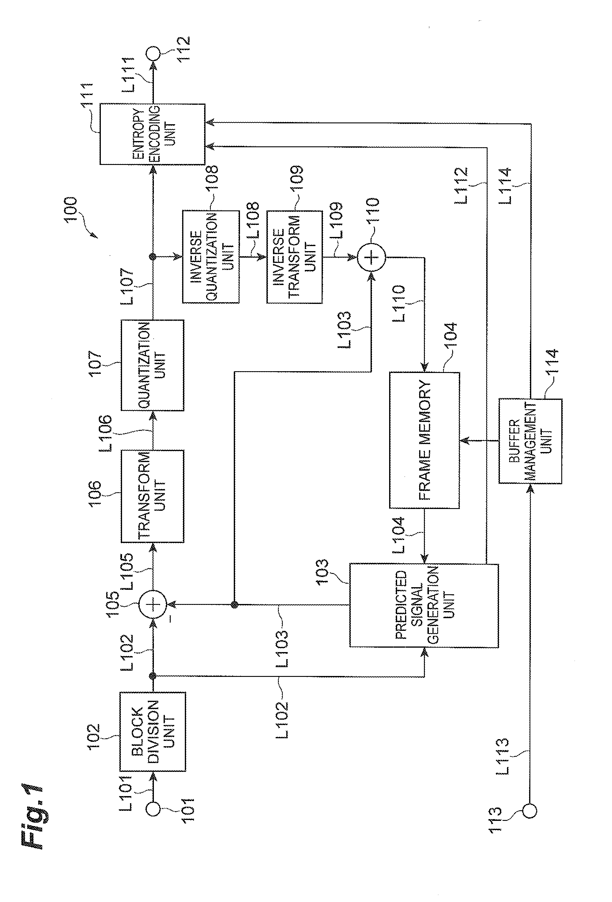
[0041]Embodiments of the video predictive coding system will be described below using FIGS. 1 to 24. FIG. 1 is a block diagram showing an example video predictive encoding device 100 according to an embodiment. As shown in FIG. 1, the video predictive encoding device 100 is provided with circuitry that includes an input terminal 101, a block division unit 102, a predicted signal generation unit 103, a frame memory (or buffer, which will also be referred to as DPB) 104, a subtraction unit 105, a transform unit 106, a quantization unit 107, an inverse quantization unit 108, an inverse transform unit 109, an addition unit 110, an entropy encoding unit 111, an output terminal 112, and a buffer management unit 114. The subtraction unit 105, transform unit 106, and quantization unit 107 can correspond to an encoding unit or circuit. The inverse quantization unit 108, inverse transform unit 109, and addition unit 110 can correspond to a reconstruction unit or circuit. As used herein, the t...


PUM


Abstract

A video predictive coding system includes a video predictive encoding device having: an input circuit to receive pictures constituting a video sequence; an encoding circuit which conducts predictive coding of a target picture using, as reference pictures, pictures encoded and reconstructed in the past, to generate compressed picture data; a reconstruction circuit to decode the compressed picture data to reconstruct a reproduced picture; picture storage to store the reproduced picture as a reference picture for encoding of a subsequent picture; and a buffer management circuit which controls the picture storage, (prior to predictive encoding of the target picture), on the basis of buffer description information BD[k] related to reference pictures used in predictive encoding of the target picture, encodes the buffer description information BD[k] with reference to buffer description information BD[m] for a picture different from the target picture, and adds encoded data thereof to the compressed picture data.

Description

[0001]This application is a continuation of PCT / JP2012 / 073090, filed Sep. 10, 2012, which claims the benefit of the filing date pursuant to 35 U.S.C. §119(e) of JP2011-228758, filed Oct. 18, 2011 and JP2011240334, filed Nov. 1, 2011, all of which are incorporated herein by reference.TECHNICAL FIELD[0002]The present disclosure relates to a video predictive encoding method, device and program, and a video predictive decoding method, device and program, and more particularly, to a description in a buffer for reference pictures to be used in inter-frame predictive encoding.BACKGROUND ART[0003]Compression coding technologies are used for efficient transmission and storage of video data. The techniques defined in MPEG-1 to 4 and ITU (International Telecommunication Union) H.261 to H.264 are commonly used for video data.SUMMARY[0004]Using encoding techniques, a picture which is used as an encoding target is divided into a plurality of blocks and then an encoding process and a decoding proc...

Claims


Application Information

Patent Timeline
IPC IPC(8): H04N19/503H04N19/50H04N19/105H04N19/134H04N19/159H04N19/423H04N19/46H04N19/463H04N19/593H04N19/61H04N19/625H04N19/70
CPCH04N19/00575H04N19/61H04N19/42H04N19/139H04N19/13H04N19/159H04N19/15H04N19/152H04N19/172H04N19/176H04N19/196H04N19/105H04N19/124H04N19/433H04N19/44H04N19/463H04N19/503H04N19/50H04N19/52H04N19/56H04N19/625H04N19/70H04N19/96H04N19/134H04N19/46
Inventor BOON, CHOONG SENGSUZUKI, YOSHINORITAN, THIOW KENG
Owner NTT DOCOMO INC
Why Eureka
Try Eureka