
Toner refill device

a refill device and toner technology, applied in optics, instruments, electromagnetography/magnetography, etc., can solve the problems of toner powder stained inside the passage forming element, and achieve the effect of promoting the discharge of toner powder and controlling the rotation speed

Active Publication Date: 2014-08-14
OCE TECH
View PDF1 Cites 11 Cited by
  • Summary
  • Abstract
  • Description
  • Claims
  • Application Information

AI Technical Summary

Benefits of technology

The present invention is for a toner refill device for printers and copiers. The invention has two main technical effects. Firstly, the closure members and the passage forming element rotate instead of move linearly, which reduces the space requirement and makes the device more compact. Secondly, a motor drive unit controls the rotation speed of the closure members to limit frictional heat and prevent toner powder from caking. Additionally, an adapter unit can be connected to the toner reservoir of the printer or copier and a wobbling device can be added to promote the discharge of toner powder from the bottle. These technical effects help to improve the functionality, reliability, and overall performance of the toner refill device.

Problems solved by technology

Inevitably, the internal walls of the passage forming element become stained with toner powder in this process.

Method used


Image

  • Toner refill device
  • Toner refill device
  • Toner refill device

Examples


Embodiment Construction

[0022]The present invention will now be described with reference to the accompanying drawings, wherein the same or similar elements are identified with the same reference numerals throughout the several views.

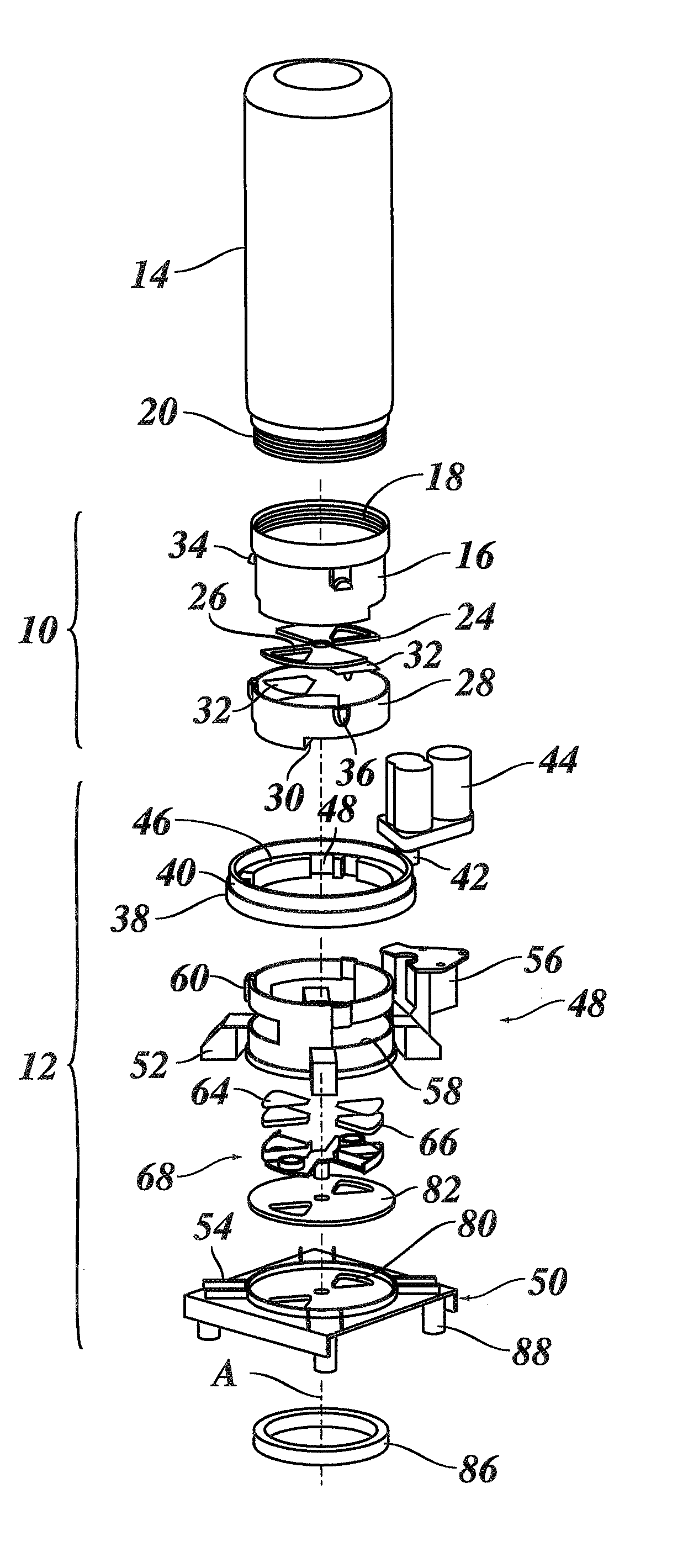
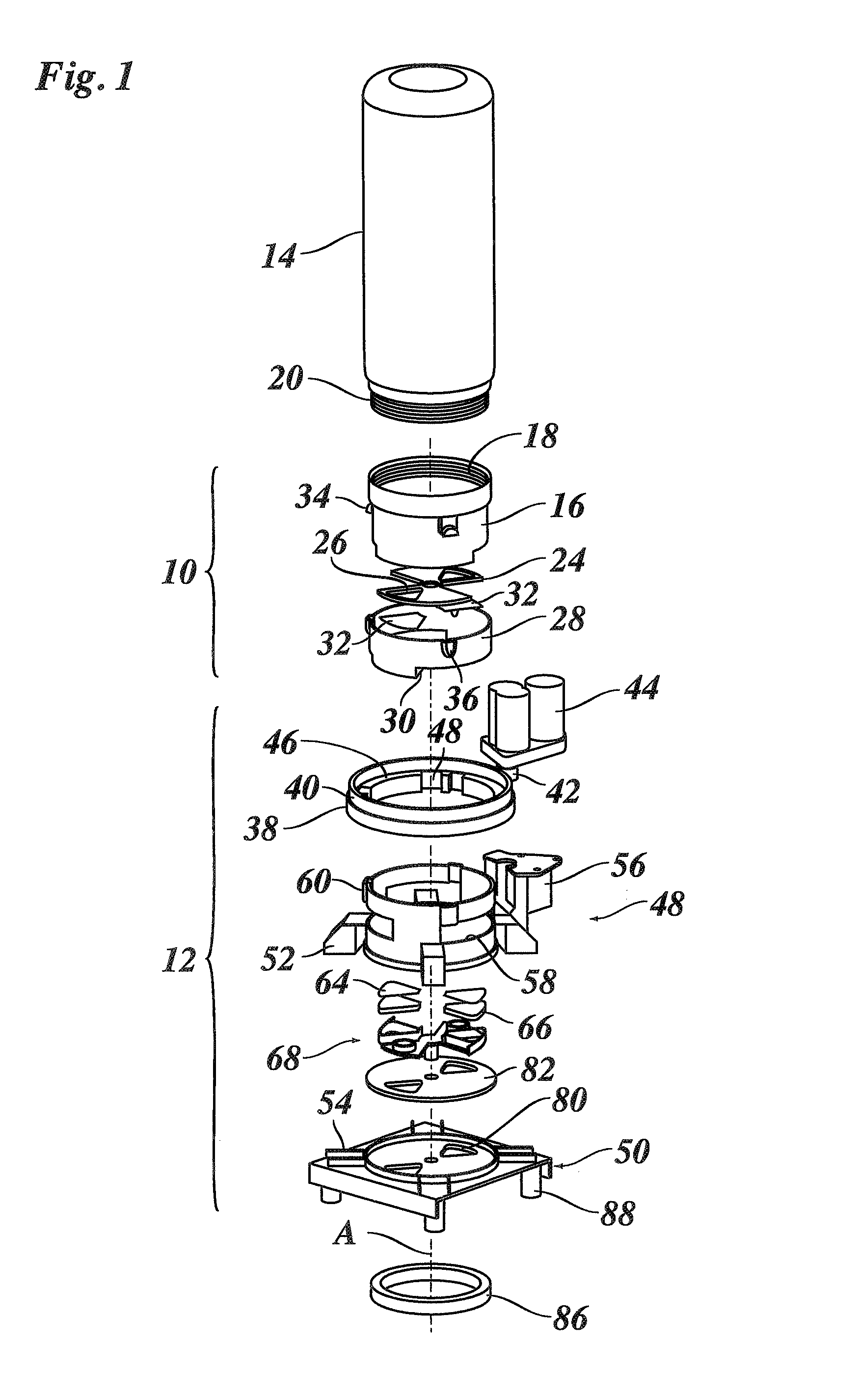
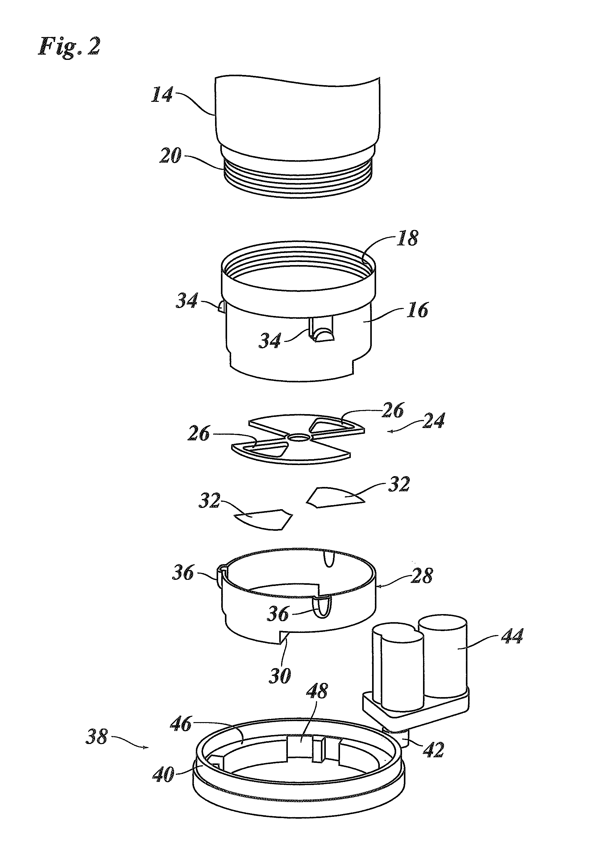
[0023]The toner refill device shown in FIG. 1 comprises a first adapter unit 10 and a second adapter unit 12 that are configured to be coupled to one another. The first adapter unit 10, which has been shown on an enlarged scale in FIG. 2, is to be attached to an open end of a toner bottle 14 and has a tubular body or cap member 16 with an internal screw-thread 18 for being threaded onto an external screw-thread 20 formed on a neck of the toner bottle 14.

[0024]At the bottom end, the cap member 16 has a bottom wall 21 (FIG. 5), which defines a first refill opening 22. A seal plate 24, which may be made of an elastic foam material, is attached to a bottom face of the cap member 16. A circular area covered by the seal 24 plate is divided into six equi-angular sectors. Two of these ...


PUM


Abstract

A toner refill device includes first and second adapter units defining first and second refill openings, and first and second closure members movable between closed positions open and closed positions to respectively close and open the refill openings. The second closure member has a passage forming element connecting the refill openings when the second closure member is in the open position. The second adapter unit defines an accommodation space for accommodating the passage forming element when the second closure member is in the closed position. The closure members are adapted to be coupled to one another for a joint movement relative to the adapter units. The closure members are rotatably supported in their respective adapter units so as to be jointly rotatable about a common axis of rotation. The second refill opening and the accommodation space are angularly offset from one another about said common axis of rotation.

Description

CROSS-REFERENCE TO RELATED APPLICATIONS[0001]This application is a Continuation of International Application No. PCT / EP2012 / 069915, filed on Oct. 9, 2012, and for which priority is claimed under 35 U.S.C. §120. PCT / EP2012 / 069915 claims priority under 35 U.S.C. §119(a) to Application No. 11185718.1, filed in Europe on Oct. 19, 2011. The entire contents of each of the above-identified applications are hereby incorporated by reference into the present application.BACKGROUND OF THE INVENTION[0002]1. Field of the Invention[0003]The present invention relates to a toner refill device comprising: a first adapter unit defining a first refill opening; a first closure member attached to the first adapter unit and movable between a closed position in which it closes the first refill opening, and a second position; a second adapter unit defining a second refill opening; and a second closure member attached to the second adapter unit and movable between a closed position in which it closes the se...

Claims


Application Information

Patent Timeline
Patent Type & Authority Applications(United States)
IPC IPC(8): G03G15/08
CPCG03G15/0894G03G15/087G03G15/0886
Inventor JANSSEN, WILLEM P.H.A.
Owner OCE TECH
Learn More