Hollow Wall Composite Tube

a composite tube and hollow wall technology, applied in the field of hollow wall composite tube, can solve the problems of buckling, single unsupported wall is subject to distortion, vibration, buckling, even cracking and splitting, etc., and achieves the effect of maintaining light weight and strength

Inactive Publication Date: 2014-08-14
FRAIDENBURGH ROBERT BURCH
View PDF0 Cites 3 Cited by
  • Summary
  • Abstract
  • Description
  • Claims
  • Application Information

AI Technical Summary

Benefits of technology

[0010]It would be advantageous to provide a composite tube having a hollow wall for light weight and strength.
[0011]It would also be advantageous to provide a composite tube resistant to vibration, while maintaining light weight.
[0012]It would also be advantageous to provide a composite tube resistant to distortion when flexed, loaded, or subjected to torque.

Problems solved by technology

When more strength is desired in a composite tube, options are limited.
Decreasing wall thickness to reduce weight can have catastrophic results.
A single unsupported wall is subject to distortion, vibration, buckling, even cracking and splitting.
Changing material can increase cost.

Method used


Image

  • Hollow Wall Composite Tube
  • Hollow Wall Composite Tube
  • Hollow Wall Composite Tube

Examples


Embodiment Construction

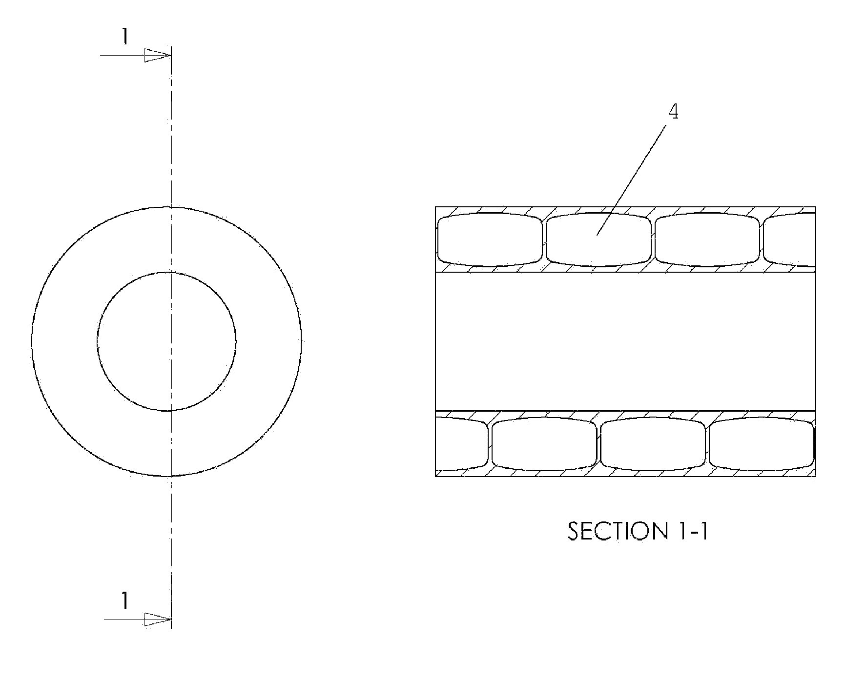
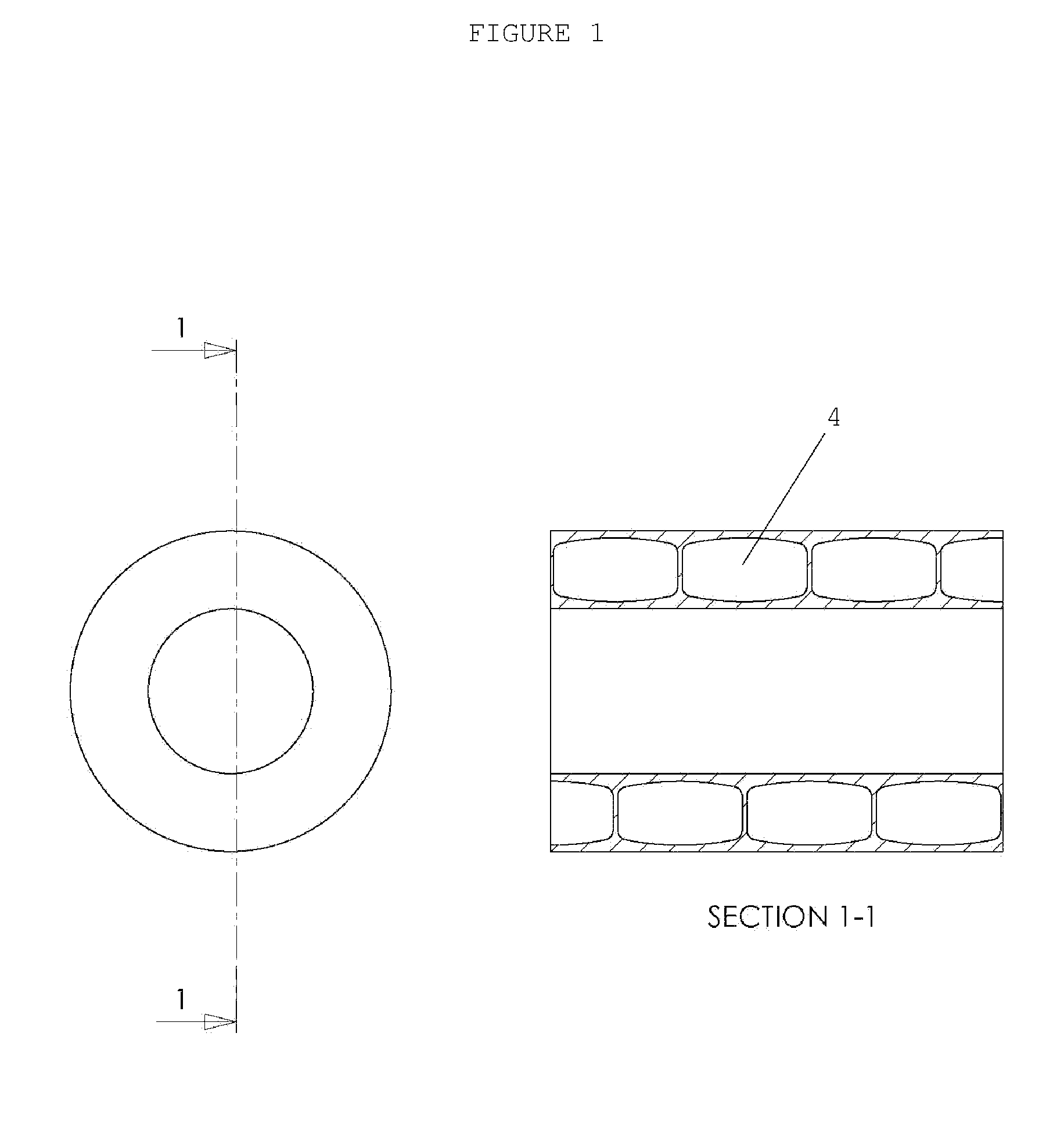
[0018]FIG. 1 is a section view of a hollow wall composite tube in accordance with the invention. The section view in FIG. 1 is cut parallel to the axis of the tube. The hollow 4 shown is arched for strength, like an architectural arch. The shape of the hollow 4 can be tuned to optimize performance in a given application. For example, if the tube is to be used as a golf club shaft, subject to severe side loads, the arch shaped hollow 4 strengthens the wall against collapse.

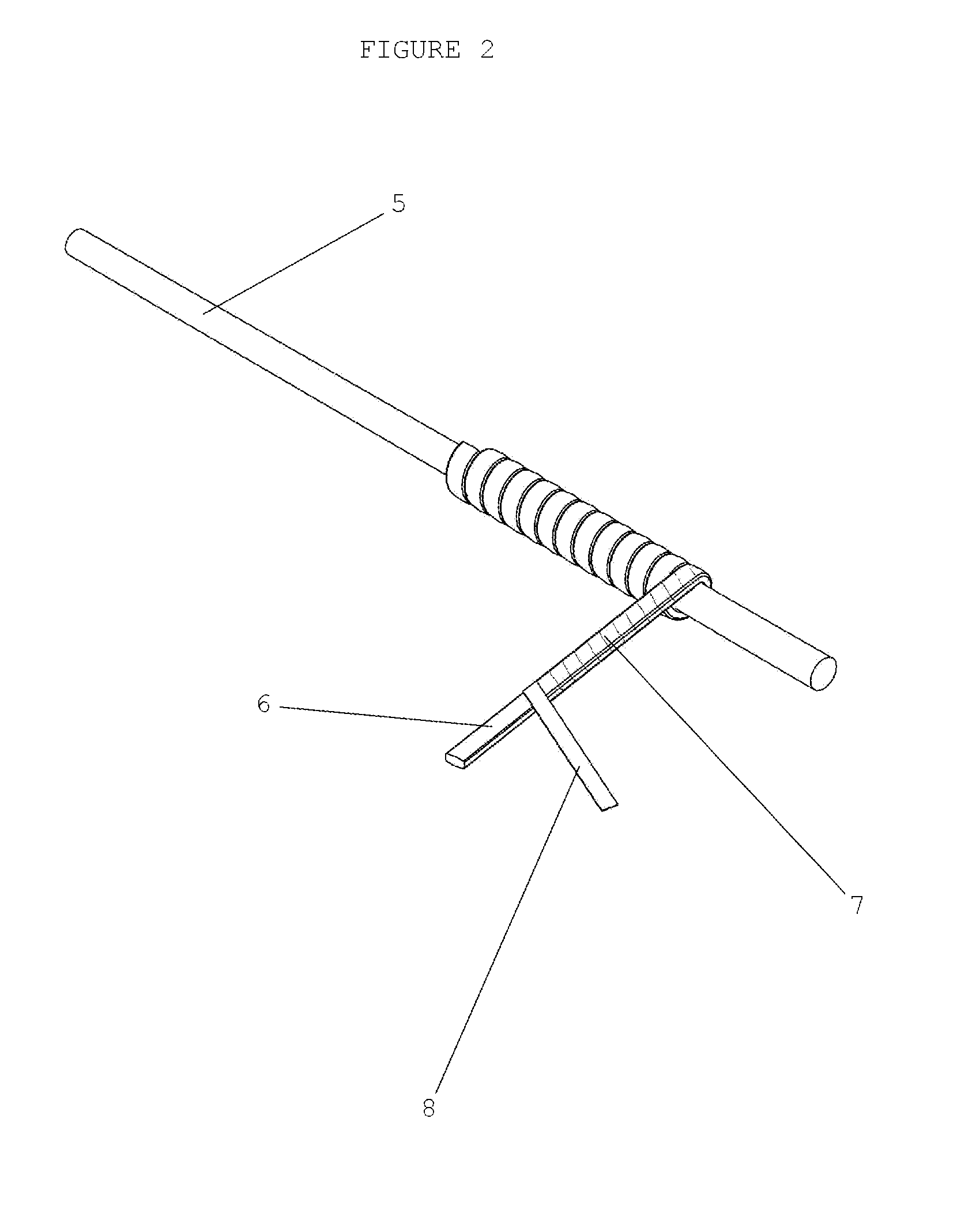
[0019]FIG. 2 is a perspective view showing constituent tube 7 being wound onto a removable mandrel 5. Also shown is constituent tube 7 being produced by spiral wrapping core 6 with tow (filaments) or fabric 8 prior to being wound on mandrel 5. Tuning of the hollow 4 shape can be accomplished by changing the shape of core 6. An elongated oval core 6 will produce an elongated oval hollow 4 after curing in a manner well known to those skilled in the art, and core 6 is removed by dissolving or melting. Likewise a round...


PUM

PropertyMeasurementUnit
shapeaaaaaaaaaa
weightaaaaaaaaaa
flexibleaaaaaaaaaa

Abstract

A one piece composite tube having a hollow wall structure. The outside and inside of the tube have a standard surface and shape for bonding or fastening. The hollow wall reduces vibration and allows consistent flexure and torsion. The shape of the hollow wall may be tuned to maintain light weight and optimize strength for a given application.

Description

RELATED APPLICATIONS[0001]The present application is a continuation-in-part application of U.S. provisional patent application, Ser. No. 61 / 606,186, filed Mar. 2, 2012, by Robert Burch Fraidenburgh, Woodside, Calif., included by reference herein and for which benefit of the priority date is hereby claimed.[0002]The present application is a continuation-in-part application of U.S. provisional patent application, Ser. No. 61 / 656,010, filed Jun. 6, 2012, by Robert Burch Fraidenburgh, Woodside, Calif., included by reference herein and for which benefit of the priority date is hereby claimed.[0003]The present application is a continuation-in-part application of U..S provisional patent application, Ser. No. 61 / 671,700, filed Jul. 14, 2012, by Robert Burch Fraidenburgh, Woodside, Calif., included by reference herein and for which benefit of the priority date is hereby claimed.FIELD OF THE INVENTION[0004]The present invention relates to products made from composite tubing and, more particul...

Claims


Application Information

Patent Timeline
Patent Type & Authority Applications(United States)
IPC IPC(8): B32B1/08
CPCB32B1/08A63B60/06A63B53/10A63B2209/02A63B59/70A63C11/227Y10T428/13Y10T428/1369Y10T428/1362B29C70/30B29K2063/00B29K2307/04B29L2023/22B29L2024/00B29L2031/52B32B2363/00B32B2597/00
Inventor FRAIDENBURGH, ROBERT BURCH
Owner FRAIDENBURGH ROBERT BURCH
Why Eureka
Try Eureka