Operation input device and method of initializing operation input device

a technology of operation input and input device, which is applied in the direction of mechanical control device, programme control, instruments, etc., can solve the problem of encoder which cannot d

Active Publication Date: 2014-08-14
OLYMPUS CORP
View PDF17 Cites 31 Cited by
  • Summary
  • Abstract
  • Description
  • Claims
  • Application Information

AI Technical Summary

Benefits of technology

[0020]According to a tenth aspect of the present invention, a method of initializing an operation input device that has two or more multi-jointed arms which have a plurality of joints in series having a degree of freedom of rotation or translation and are configured so that a position and an orientation of a distal end thereof relative to a proximal end thereof are changed, and a detection unit which is provided in each of the plurality of joints to detect a joint movement amount that represents a movement of each of the plurality of joints by a rotation angle or a translational displacement from an unknown initial joint value, includes: a holding process of holding the proximal ends of the multi-jointed arms in a state in which a relative positional relationship between

Problems solved by technology

However, in order to promote a low cost, in many cases,

Method used


Image

  • Operation input device and method of initializing operation input device
  • Operation input device and method of initializing operation input device
  • Operation input device and method of initializing operation input device

Examples


first embodiment

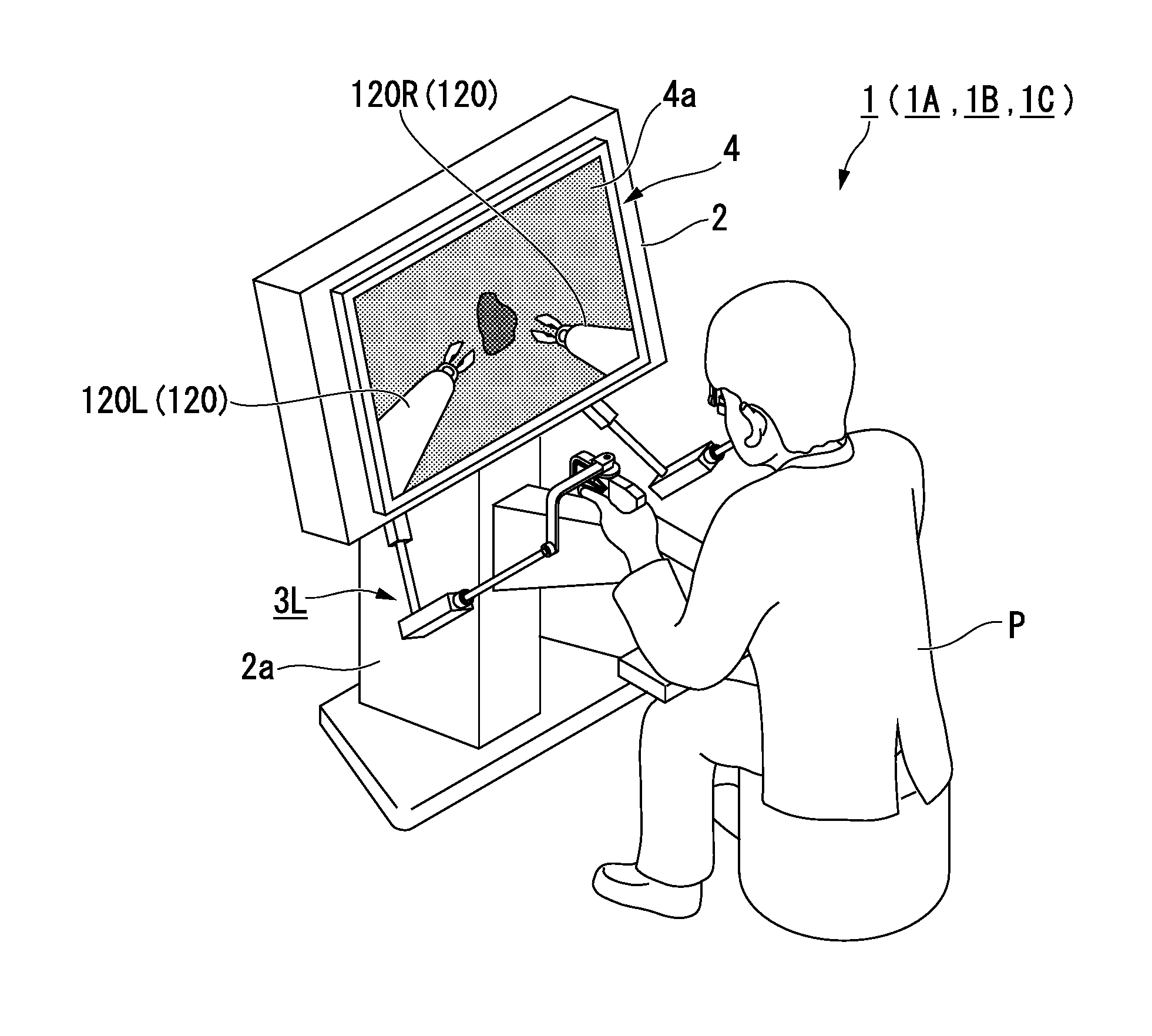
[0046]An operation input device according to a first embodiment of the present invention will be described.

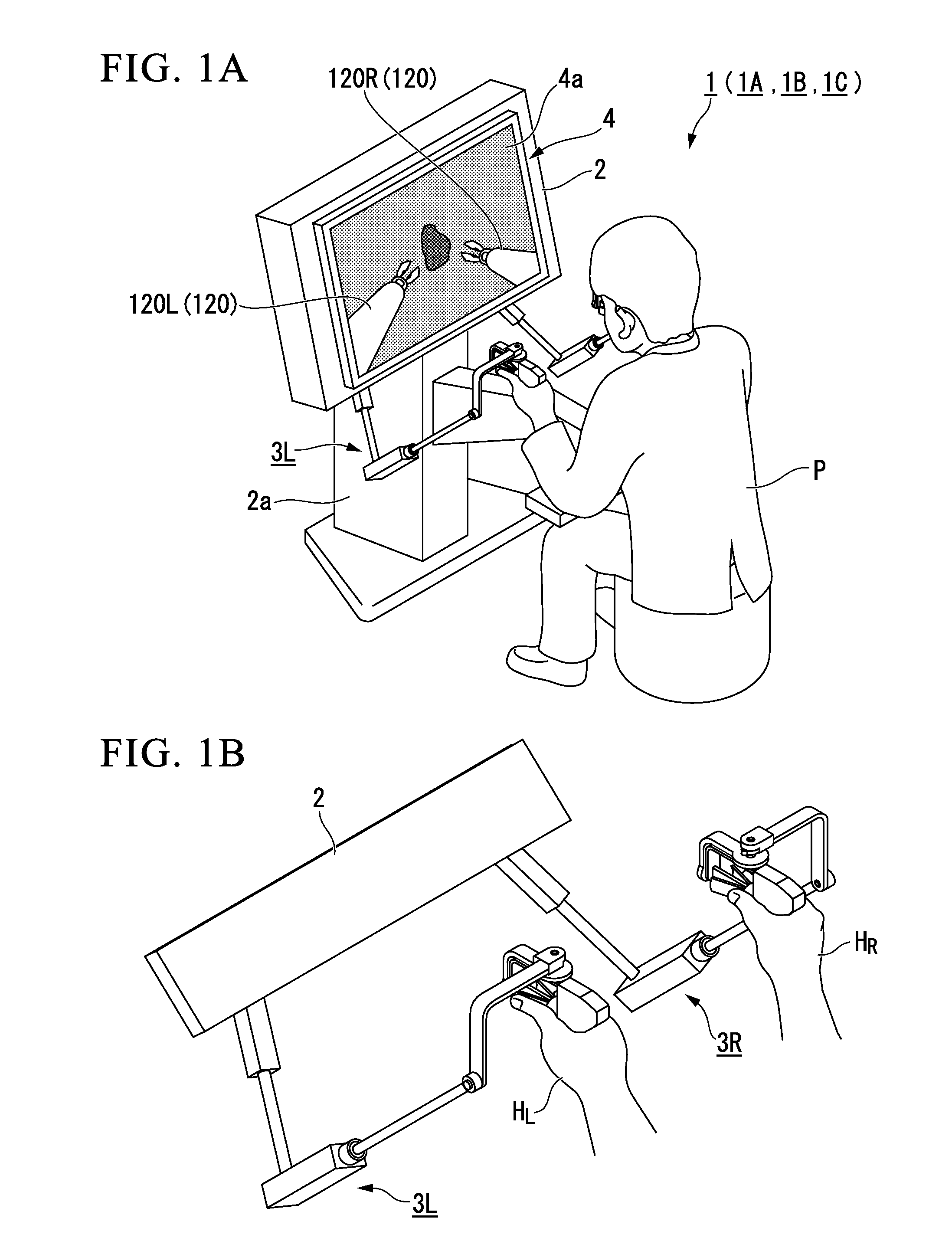
[0047]FIG. 1A is a schematic perspective view that illustrates an example of the operation input device according to the first embodiment of the present invention. FIG. 1B is a perspective view of main parts of the operation input device according to the first embodiment of the present invention.

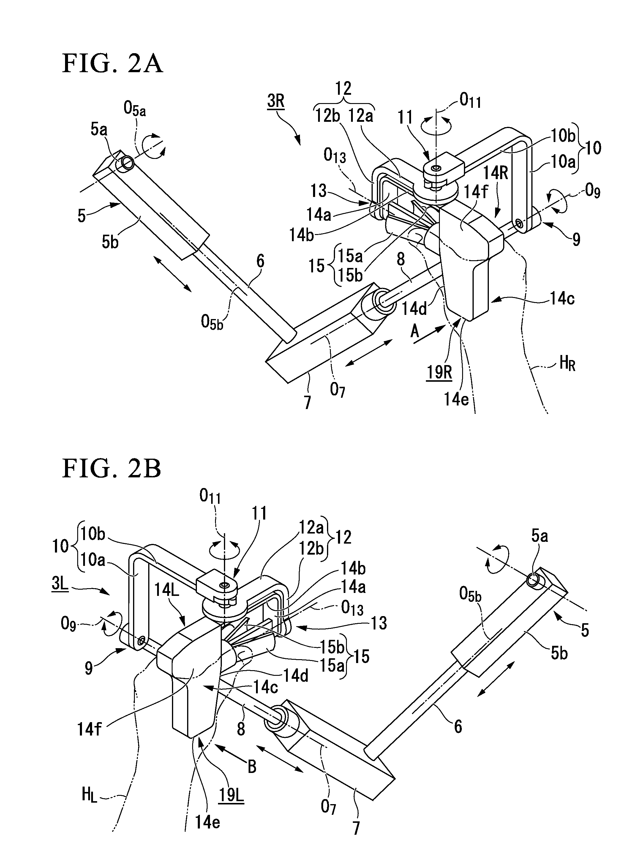
[0048]FIGS. 2A and 2B are schematic perspective views that illustrate a configuration of a multi-jointed arm of the operation input device according to the first embodiment of the present invention. FIG. 3A is a view in a direction of an arrow A in FIG. 2A. FIG. 3B is a view in a direction of an arrow C in FIG. 3A. FIG. 4A is a view in a direction of an arrow B in FIG. 2B. FIG. 4B is a view in a direction of an arrow D in FIG. 4A. FIG. 5A is a schematic plan view that illustrates a state in which engagement units of the operation input device according to the first embodiment of the pre...

first modified example

[0252]Next, an operation input device according to a modified example (first modified example) of the present embodiment will be described.

[0253]FIG. 10 is a schematic perspective view that illustrates a configuration of a main part of the operation input device according to the modified example (first modified example) of the first embodiment of the present invention. FIG. 11 is a plan view of an intermediate member that is used in the operation input device according to the modified example (first modified example) of the first embodiment of the present invention.

[0254]FIG. 10 illustrates a configuration of the main part of a master manipulator 1A (operation input device) according to the present modified example.

[0255]The master manipulator 1 according to the first embodiment is an example of a case in which the engagement units 19R and 19L directly engage the right hand operation arm 14R and the left hand operation arm 14L to fix the mutual relative position. However, a master m...

second embodiment

[0270]An operation input device according to a second embodiment of the present embodiment will be described.

[0271]FIGS. 12A and 12B are a schematic perspective view and a diagram for describing an operation that illustrate the configuration of the main parts of the operation input device according to the second embodiment of the present invention. FIGS. 13A and 13B are schematic perspective views that illustrate a configuration of an engagement unit of the operation input device of the second embodiment of the present invention.

[0272]In a master manipulator 1B (operation input device) according to the present embodiment, the engagement units 19R and 19L of the master manipulator 1 according to the first embodiment are omitted as the main parts thereof are shown in FIG. 12A, and a detection unit F13 (see FIG. 6) capable of detecting an absolute rotation angle from the reference of the joint coordinate system is included instead of the respective detection units E13. The master manip...


PUM


Abstract

An operation input device that has multi jointed arms includes: a holding unit that holds proximal ends of the multi-jointed arms in a state in which a relative positional relationship between the proximal ends is fixed; a detection unit that detects a joint movement amount that represents a movement of a joint by a rotation angle or a translational displacement from an unknown initial joint value; engagement units that are provided in distal ends of the multi jointed arms; a data acquisition unit that acquires a plurality of sets of joint movement amounts detected by the detection unit in a time series when engaging and moving the distal ends; and an initial value calculation unit that calculates the unknown initial joint value under a condition that a relative positional relationship between the distal ends is fixed via the engagement units.

Description

[0001]This application is a continuation application based on a PCT Patent Application No. PCT / JP2012 / 077381, filed Oct. 17, 2012, whose priority is claimed on Japanese Patent Application No. 2011-228677 filed Oct. 18, 2011. The contents of both the PCT Application and the Japanese Application are incorporated herein by reference.BACKGROUND OF THE INVENTION[0002]1. Field of the Invention[0003]The present invention relates to an operation input device and a method of initializing the operation input device. The present invention relates to, for example, an operation input device that has a plurality of multi-jointed arms and performs an operation input by moving the plurality of multi-jointed arms, and a method of initializing the operation input device.[0004]2. Description of Related Art[0005]In the related art, in an apparatus (for example, a remote control robot, an operation input device for performing a surgical assistant of a surgical operation or the like) in which an actuatin...

Claims


Application Information

Patent Timeline
IPC IPC(8): A61B19/00B25J13/02G05G9/047B25J3/00
CPCA61B19/2203B25J3/00A61B2019/2223G05G9/04737A61B2019/2269B25J13/02G06F3/0346A61B34/30A61B34/37A61B34/74
Inventor KISHI, KOSUKE
Owner OLYMPUS CORP
Why Eureka
Try Eureka