Internal Floating Roof for Covering Fluid Bodies in Storage Tanks

a technology of floating roof and storage tank, which is applied in the direction of transportation and packaging, packaging, and large containers, can solve the problems of health, safety or fire hazards of liquids, objectionable odor of other liquids, sulfuric acid-containing liquids, and potentially hazardous atmosphere for stored liquids, so as to eliminate any potential for gas or vapor emissions

Active Publication Date: 2014-08-21
ROSENKRANTZ DAVID JON
View PDF1 Cites 7 Cited by
  • Summary
  • Abstract
  • Description
  • Claims
  • Application Information

AI Technical Summary

Benefits of technology

[0018]The internal floating roof composed of the panel systems may also include further sealing means along the top side of the abutting C-shaped beams to virtually eliminate any potential for gas or vapor emissions through the sidewall joint. The sealing means can be a running weld along the joint or a resilient sealing caulk or similar compound that is resistant to the stored liquid. The C-shaped sidewalls may be made from metals, such as aluminum, steel or stainless steel, or from extruded fiberglass, carbon or graphite composites or similar synthetic materials having suitable physical properties.

Problems solved by technology

Escaping vapors of many hydrocarbon based liquids can present health, safety or fire hazards.
Other liquids, particularly those containing sulfur, can present an objectionable odor when permitted to evaporate freely.
If any mechanical joints, seams or holes exist or are created through continued use in the membrane, liquid vapors from the vapor space below the membrane can leak through the membrane to the ambient atmosphere above the membrane creating a potentially hazardous atmosphere as well as an evaporative condition for the stored liquid.
While this is an improvement in creating a floating barrier for retaining the liquid in a non-evaporative state, thus controlling evaporation, there still exists the problem of mechanical joints, seams and holes that provide points of leakage.
However, there remain structural flaws that need to be addressed to further reduce evaporation, collection of volatile gases below and in the enclosed panel spaces, and reduce the vertical height to achieve less overall weight increasing the buoyancy and permitting greater storage capacity in the tank.
One of the noticed problems with the present designs for floating roof panels is the penetration through the hook and distending flange attachment between panels.
Another of the problems with the present designs for floating roof panels is the presence of fasteners in a potential vapor escape path that allow the passage of vapors to the space above the floating roof.
Another of the problems is the leakage of the liquid and / or vapors into the interior space of the composite panel creating a potentially hazardous condition and defeating the buoyancy characteristics for that panel.
One other problem has been the additional buoyant members placed beneath the floating roof to maintain its buoyancy where required (typically at the outer edge of the floating roof where additional equipment is installed on top of the floating roof) and the subsequent loss of contact with the liquid surface.
The buoyant members continually were in need of replacement as the liquids contained in the tanks seeped into them and destroyed their buoyancy.
One additional problem is vapor leakage through the elongated mechanical seams between the edge members of the panels.
Evaporative leakage is a problem as vapors can build up in the ambient atmosphere within the tank above the floating roof.
If the seams are not absolutely tight, vapor can leak between the adjoining surfaces of the edge members even if they look as if there is no visible space therebetween.

Method used


Image

  • Internal Floating Roof for Covering Fluid Bodies in Storage Tanks
  • Internal Floating Roof for Covering Fluid Bodies in Storage Tanks
  • Internal Floating Roof for Covering Fluid Bodies in Storage Tanks

Examples


Embodiment Construction

[0029]The following detailed description is of the best presently contemplated mode of carrying out the invention. The description is not intended in a limiting sense, and is made solely for the purpose of illustrating the general principles of the invention. The various features and advantages of the present invention may be more readily understood with reference to the following detailed description taken in conjunction with the accompanying drawings.

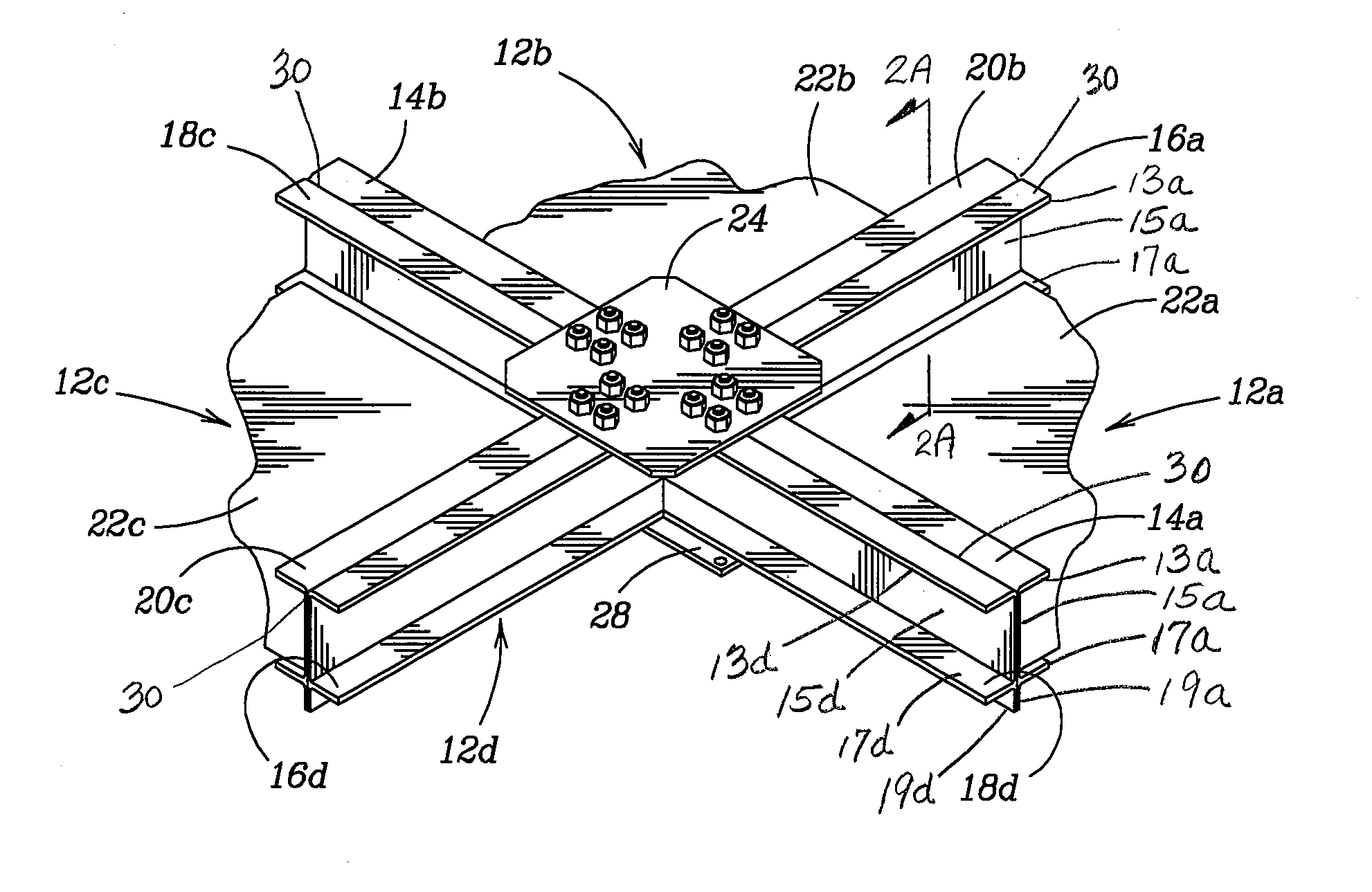
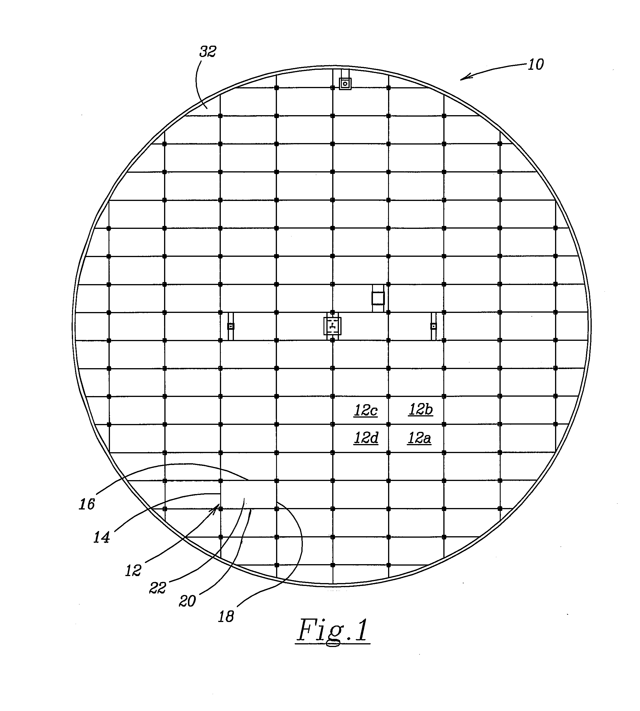
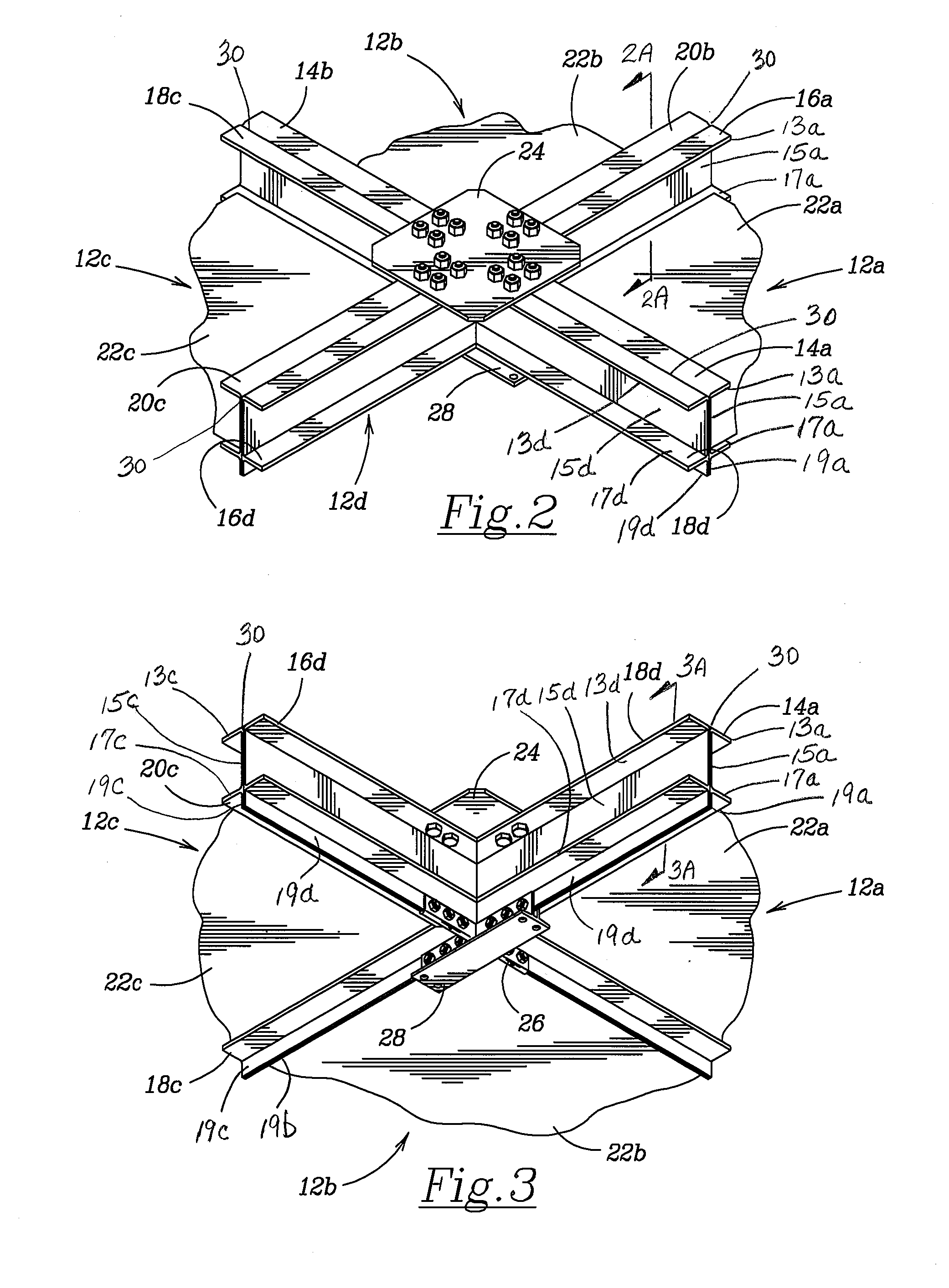
[0030]Referring now to the drawings in detail, where like numerals refer to like parts or elements, there is shown in FIG. 1 the internal floating roof 10 of the present invention. The internal floating roof 10 is joined together from a plurality of individual reinforced panels such as the reinforced panel 12 indicated in FIG. 1. The reinforced panel system 12 is shown as a rectangular panel system, but other geometric shapes can be utilized, e.g. triangular, square, diamond or other parallelogram, hexagonal, etc. The reinforced panel...


PUM


Abstract

An internal floating roof for use in large volatile or hazardous liquid storage tanks constructed of a plurality of open-top panel systems including C-shaped beams each having a vertical sidewall and flanges extending inward along the top and bottom of the beams with a bottom flange extending the vertical wall downward beyond the bottom. The panel systems are secured together using top and bottom brackets to construct a rigid, non-flexing roof structure to contain the hazardous gases and vapors beneath the floating roof without creating alternative escape pathways along the respective joints or seams between the panel systems. An additional seal in the form of a weld or resilient sealing member may be used along the joint between adjacent beams to further secure against leaking.

Description

RELATED U.S. APPLICATION DATA[0001]The present invention is a continuation-in-part of U.S. non-provisional patent application Ser. No. 13 / 490,230 filed on Jun. 6, 2012, now abandoned.BACKGROUND OF THE INVENTION[0002]The present invention relates to an internal floating roof located atop a fluid body in a fluid storage tank. Bulk fluids such as petroleum and other liquid fuel and chemical products are often stored in large cylindrical tanks. These tanks are commonly designed with internal floating roofs or covers to minimize product losses through leakage or evaporation to the atmosphere. The present invention describes a floating roof that is comprised of integral panels having a lower profile than existing floating roofs.[0003]A large number of industrial processes require the use of substantial quantities of volatile liquids such as gasoline, alcohol, etc. The industries utilizing these processes store a wide range of volatile liquids in large storage vessels. The storage vessels ...

Claims


Application Information

Patent Timeline
Patent Type & Authority Applications(United States)
IPC IPC(8): B65D88/34
CPCB65D88/34
Inventor ROSENKRANTZ, DAVID JON
Owner ROSENKRANTZ DAVID JON
Why Eureka
Try Eureka