Muzzleloader firearm system

a firearm system and muzzleloader technology, applied in the field of muzzleloading firearms, can solve the problems of cumbersome foregoing process, significantly less range of firearms, and generally less accurate, and achieve the effect of quick removal

Inactive Publication Date: 2011-02-01
RICHARDS MARLOWE R
View PDF41 Cites 25 Cited by
  • Summary
  • Abstract
  • Description
  • Claims
  • Application Information

AI Technical Summary

Benefits of technology

[0016]It has been recognized that it would be advantageous to develop a new type of breech plug that may be quickly removed without tools.
[0018]It has also been recognized that it would be advantageous to have a mechanism for rapidly extracting a spent primer from the primer recess in the breech plug, which will eliminate any potential for damaging the firearm.
[0019]In various embodiments, the present invention provides a breech plug on a muzzleloader firearm that can be removed without tools in about one second. The ease and speed of removal not only facilitates cleaning of the barrel, but enables the shooter to easily expel misfired charges through the breech, rather than attempting to extract it through the muzzle. The present application also provides a mechanism for quickly and safely extracting primers from the primer recess in the breech plug. The primer extractor may be used with breech plugs of both the conventional threaded type and the new quickly-removable type.
[0026]In some embodiments of the breech plug the lugs are unitary with a shank portion that has a diameter only slightly less than the barrel bore diameter. This clearance is, ideally, just sufficient to provide a non-interference sliding fit. A circumferential shoulder portion is positioned between and unitary with both the shank portion and a head portion. The circumferential shoulder portion, which fits into a recess at the breech end of the barrel, complicates the exit route of any combustion gases which may escape through the clearances between the breech plug and the barrel by diverting them around two 90-degree corners. The breech end of the barrel is also equipped with an annular lip that fits into a circumferential groove in the head portion of the breech plug, thereby routing any escaping gases around three additional 90-degree corners. Using these techniques, the leakage of combustion gases between the rife bore and the periphery of the breech plug is minimized. Other types of gas seals may also be used. One or more O-ring seals, a compressible metal sealing ring, or a crushable metal sealing ring may also be used in place of, or in combination with escape route diversion seals.

Problems solved by technology

However, the President did not think that ban went far enough, and so he proposed new gun legislation targeting shotguns and rifles.
In addition, because black-powder firearms have significantly less range and are generally less accurate than smokeless, breech-loading firearms, most states have established special seasons for muzzleloader hunting that are more favorable than those allotted to breechloader hunters.
However, the most significant factor in the growing popularity of muzzleloader firearms is almost certainly the challenge associated with the use of a single shot rifle during the hunt.
Pulling the trigger releases the hammer, which strikes the frizzen, which then folds back, thereby showering the powder in the pan with sparks.
The foregoing process is as cumbersome as it sounds.
These types of guns have specific limitations.
Loading such a gun is considerably more cumbersome and time-consuming than loading cartridges into a breechloader.
In-line rifles are nothing new.
Some flintlocks used in-line ignition as far back as the 1700s, although the lack of sufficiently powerful springs to drive the in-line hammers probably kept them from supplanting side-hammer rifles.
The Wolverine, however, had a long, heavy octagonal barrel and never caught on with shooters.
All muzzleloading firearms do not have removable breech plugs.
One of the problems associated with conventional threaded breech plugs is that removal of the plug requires the use of a wrench or other special tool.
A break-open type receiver or falling block action muzzleloader can involve different steps to remove the breech plug, but also present difficulties with respect to removal of the breech plug.
Another problem related to black power firearms is the difficulty of removing spent primers (often referred to as primer caps) from the primer recess in the rear end of the breech plug.
Difficult to manually remove from the recess before they are fired, they must invariably be pried from the recess with a tool after they are fired due to expansion of the brass primer casing.
If extreme care is not used during the extraction process, the rifle will sustain some degree of mechanical damage.
More are certainly possible, but increase the complexity and difficulty of the machining process, with little or no return for the added expenditure of effort.
In fact, because radiused cuts are produced by most machine tools, the total amount of surface area available for lugs and lug retaining structures may actually decrease as the number of lugs increases.
Although it is conceivable that a single lug entry cutout may be used for a single lug retaining structure, a breech plug having a single lug would be unable to radially distribute the load to the barrel, thereby resulting in a tipping force concentrated at a point on the outer edge of the breech plug.
Although the design of center-rear portion of the lugged breech plug must be specifically modified to accept the various types of primers, the lugged structure which permits quick removal of the plug is entirely unaffected by such modifications.
The circumferential shoulder portion, which fits into a recess at the breech end of the barrel, complicates the exit route of any combustion gases which may escape through the clearances between the breech plug and the barrel by diverting them around two 90-degree corners.

Method used


Image

  • Muzzleloader firearm system
  • Muzzleloader firearm system
  • Muzzleloader firearm system

Examples


first embodiment

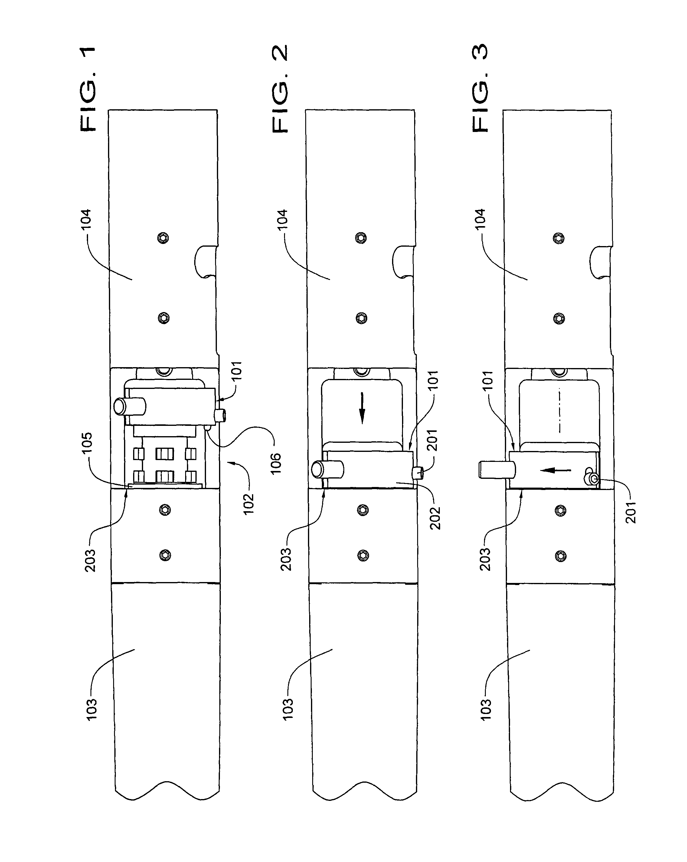
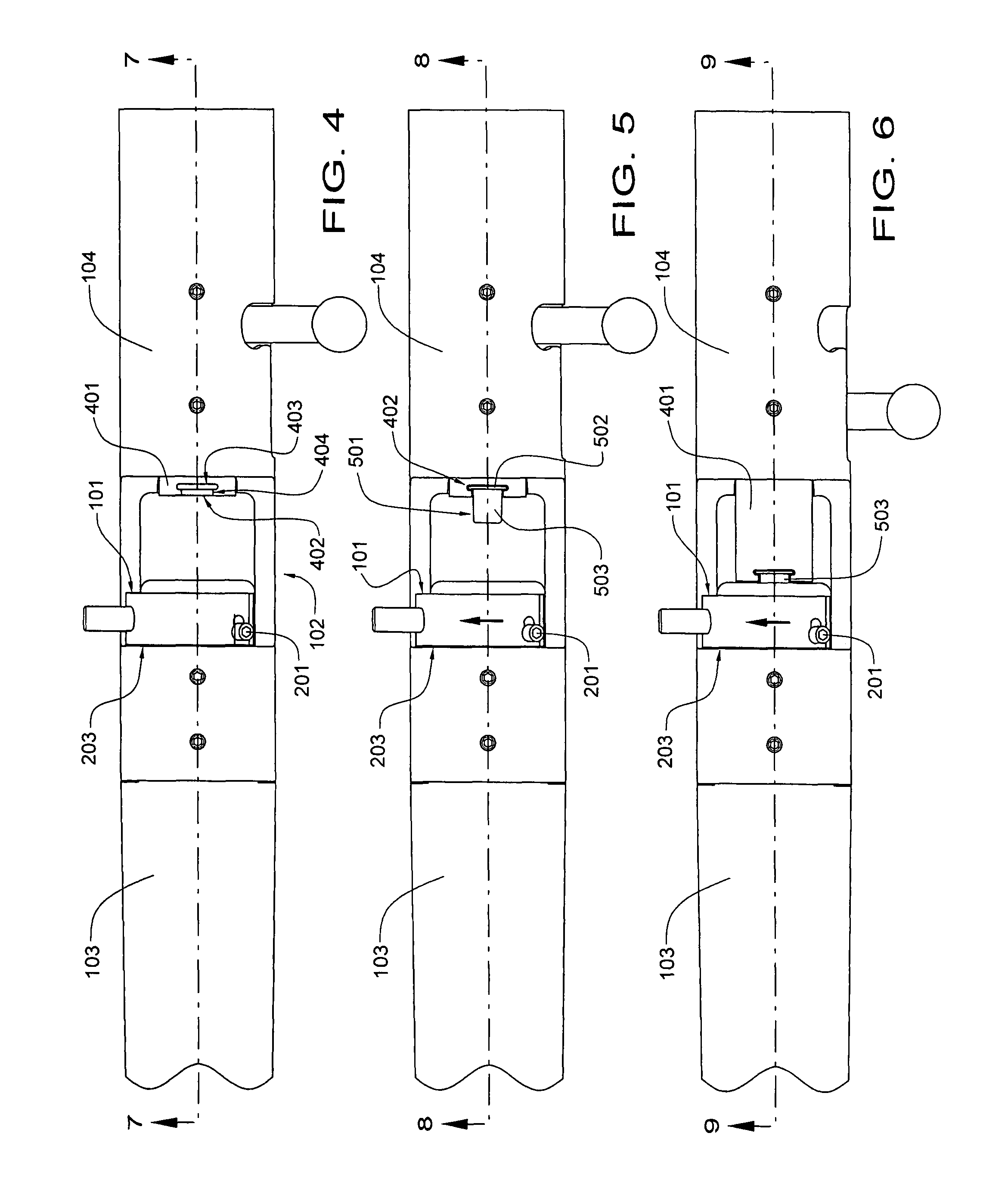
[0145]Referring now to FIGS. 57 through 60, a first embodiment detent mechanism 5701 is used to lock an easily-removable breech plug within the breech of a muzzleloader rifle. The detent mechanism includes a ball bearing 5702, a detent pin 5703 that is upwardly biased by a detent spring 5704, and a set screw 5705 which permits the detent pin 5703 to be moved vertically within the confines of a vertical notch 5706. When the detent pin 5703 is at the upward limit of its travel, the ball bearing 5702 is thrust outwardly by the full diameter of the detent pin 5703 through an aperture 5801 in the breech plug 5802. When depressed by a shooter, the ball bearing 5702 falls into a recess 5707 in the detent pin 5703.

[0146]Referring now to FIG. 60 in particular, the rear face of the breech plug 5802 incorporates a semi-circular slot 6001, which acts as a safety lock and prevents the bolt of a bolt action muzzleloader rifle from being fully closed if the breech plug is not in its locked positio...

second embodiment

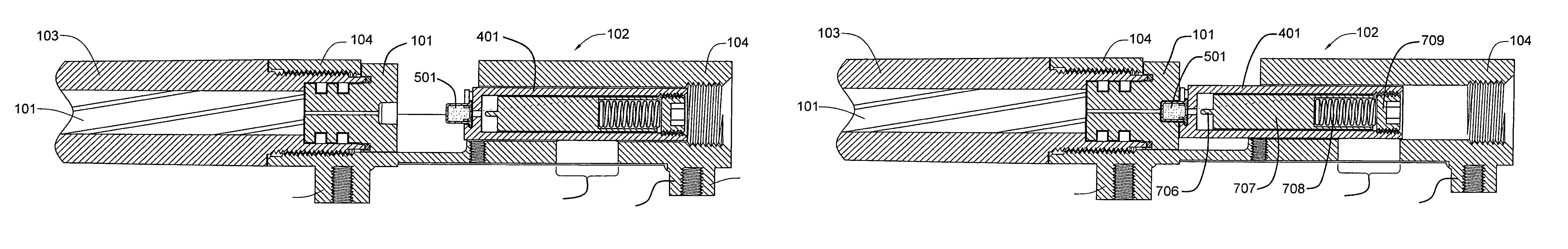
[0147]Referring now to FIGS. 61 through 68, a second embodiment detent mechanism 6401 includes a driving detent pin 6101, a detent spring 6102, and a driven detent pin 6301, which locks the breech plug 6302 within the breech of the rifle barrel. It will be noted that the spring-loaded driving detent pin 6101 has a 45-degree-angle driving tab 6103 that perpendicularly intersects a 45-degree-angle drive groove 6303 on the driven detent pin 6301. Both the driving detent pin 6101 and the driven detent pin 6301 slide within their own cylindrical recesses in the breech plug 6302. The spring loading causes the sliding driven detent pin 6301 to urge its forward end 6304 into a semi-spherical recess (not shown) on the breech end of the rifle barrel. When the driving detent pin 6101 is depressed, the detent pin retracts the driven pin 6101 from the semi-cylindrical recess in the barrel, thereby permitting the breech plug 6302 to be rotated to its unlocked position. A set screw 6305 retains th...


PUM


Abstract

Various embodiments of a muzzleloader firearm system are claimed and described.

Description

PRIORITY CLAIM[0001]The present application claims priority from U.S. provisional patent application Ser. No. 60 / 817,574, filed on Jun. 28, 2006, and entitled MUZZLELOADER HAVING A BREECH PLUG REMOVABLE WITHOUT TOOLS AND A PRIMER INSERTER / EXTRACTOR.BACKGROUND[0002]1. Field of the Invention[0003]This disclosure relates generally to firearms and, more particularly, to muzzle-loading firearms having inline ignition systems and a removable breech plug.[0004]2. Related Art[0005]Early in 1968, U.S. President Lyndon B. Johnson signed into law the Omnibus Crime Control Bill, which included sundry curbs on handguns, including a ban on the interstate mail-order sale thereof. However, the President did not think that ban went far enough, and so he proposed new gun legislation targeting shotguns and rifles. After prolonged and heated debate, Congress finally enacted the strongest gun control legislation in the nation's history on October 22 of that year. As finally approved, the legislation: ou...

Claims


Application Information

Patent Timeline
Patent Type & Authority Patents(United States)
IPC IPC(8): F41C9/08
CPCF41A3/22F41A3/24F41A3/30F41A3/74F41A9/46F41A21/12F41C9/08F42B5/38
Inventor RICHARDS, MARLOWE R.
Owner RICHARDS MARLOWE R
Why Eureka
Try Eureka