Method and apparatus for probe sensor assembly

a technology of probe sensor and assembly method, which is applied in the field of bracket system, can solve the problems of less accurate detection of the elements of the reluctor as it spins in relation to the magnetic sensor, more noise-induced failure of the sensor operation, and inability to detect the elements of the reluctor in the direction of the magnetic sensor, etc., and achieve the effect of eliminating any potential air gap

Inactive Publication Date: 2005-02-08
DELPHI TECH INC
View PDF17 Cites 17 Cited by
  • Summary
  • Abstract
  • Description
  • Claims
  • Application Information

AI Technical Summary

Benefits of technology

A method and apparatus for assembling a magnetic sensor using snap-fit assembly and a bracket to eliminate any potential air gap as a result of the snap-fit assembly. In an exemplary embodiment, a sensor package includes a sensor component for electromagnetic sensing having a sensor body with a sensor tip at one end. A sensor housing having a cavity for receiving the sensor component is disposed in a substrate and is aligned with an object to be sensed. The housing further includes a snap-fit interface with the sensor component that is configured to admit and secure the sensor tip during assembly thereof. A bracket is mechanically fixable to the substrate at a first end and is in operable communication with the sensor tip at a second end. The bracket is configured to bias the sensor tip towards the object to be sensed for elimination of an internal air gap between the sensor tip and housing formed during assembly thereof.

Problems solved by technology

Over such a range of air gaps, the sensor output signal decreases more than ten times. The signal attenuation at large air gaps makes the sensor operation more prone to noise induced failures as well as less accurate in detecting the elements of the reluctor as it spins in relation to the magnetic sensor.
Both of these factors are often unacceptable in critical engine control and diagnostic applications.
However, in the majority of production cases, the stack-up of tolerances of the many different components randomly cause internal air gaps that influence the net size of the air gap, which consequently precludes achieving, at each assembly, a precisely predetermined external air gap between the magnetic sensor and the reluctor by mere assembly of the parts.
As a result, because of the random variations caused by accumulation of tolerances, mere assembly of the parts risks damaging interference between the magnetic sensor and reluctor on the one hand, and inaccurate readings associated with too large a net air gap on the other hand.
To lessen all the tolerances so that mere assembly assures, at each assembly, the optimum external air gap is physically difficult to obtain and involves costs associated with manufacturing such precise parts.
The majority of magnetic sensors used in automotive applications involve non-adjustable air gap placement, wherein the stack-up of tolerances results in an internal air gap that causes deviation from the optimal external air gap.
This method is time consuming.
In the event the magnetic sensor must be re-installed, an abraded gauging layer cannot again provide position location for the sensor tip, as it was formerly able to do when it was unabraded.
This results in waste of otherwise good sensors and unnecessary expense for the customer or warranty provider.
Otherwise, an internal air gap is created reducing the effectiveness of the sensor by altering the net air gap between the sensor tip and the reluctor.
These approaches prove costly and timely, as well as lacking in longevity.

Method used


Image

  • Method and apparatus for probe sensor assembly
  • Method and apparatus for probe sensor assembly
  • Method and apparatus for probe sensor assembly

Examples


Embodiment Construction

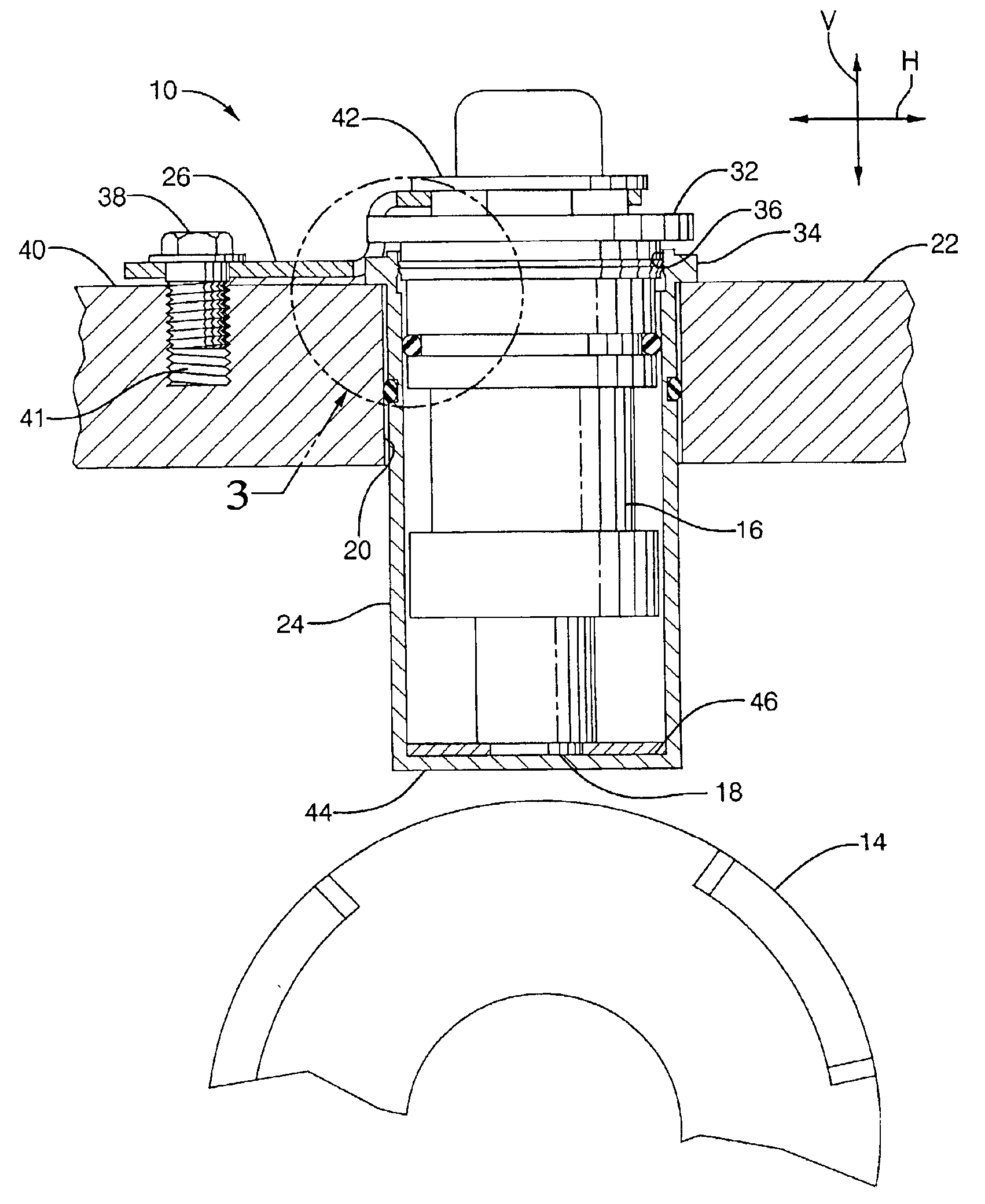
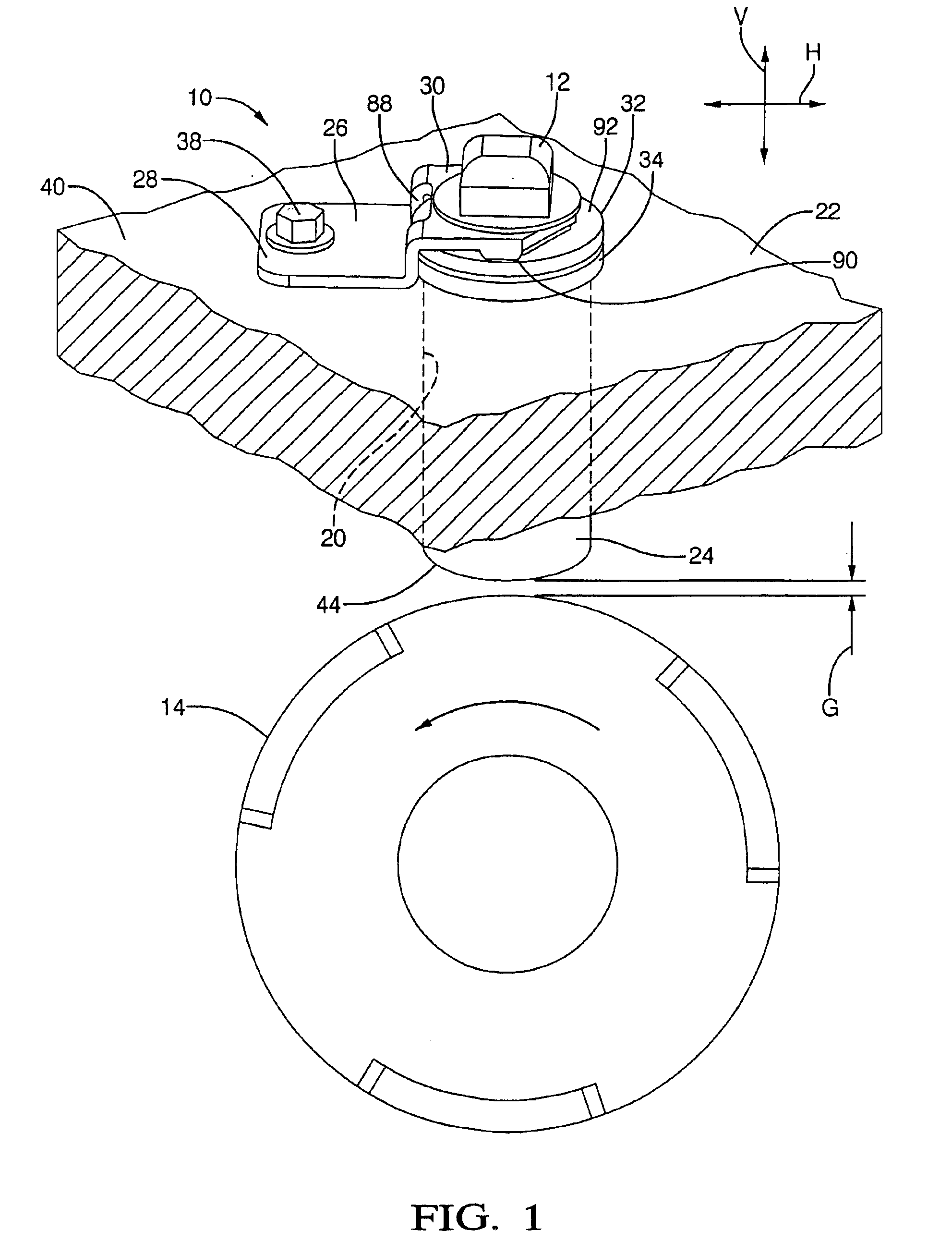
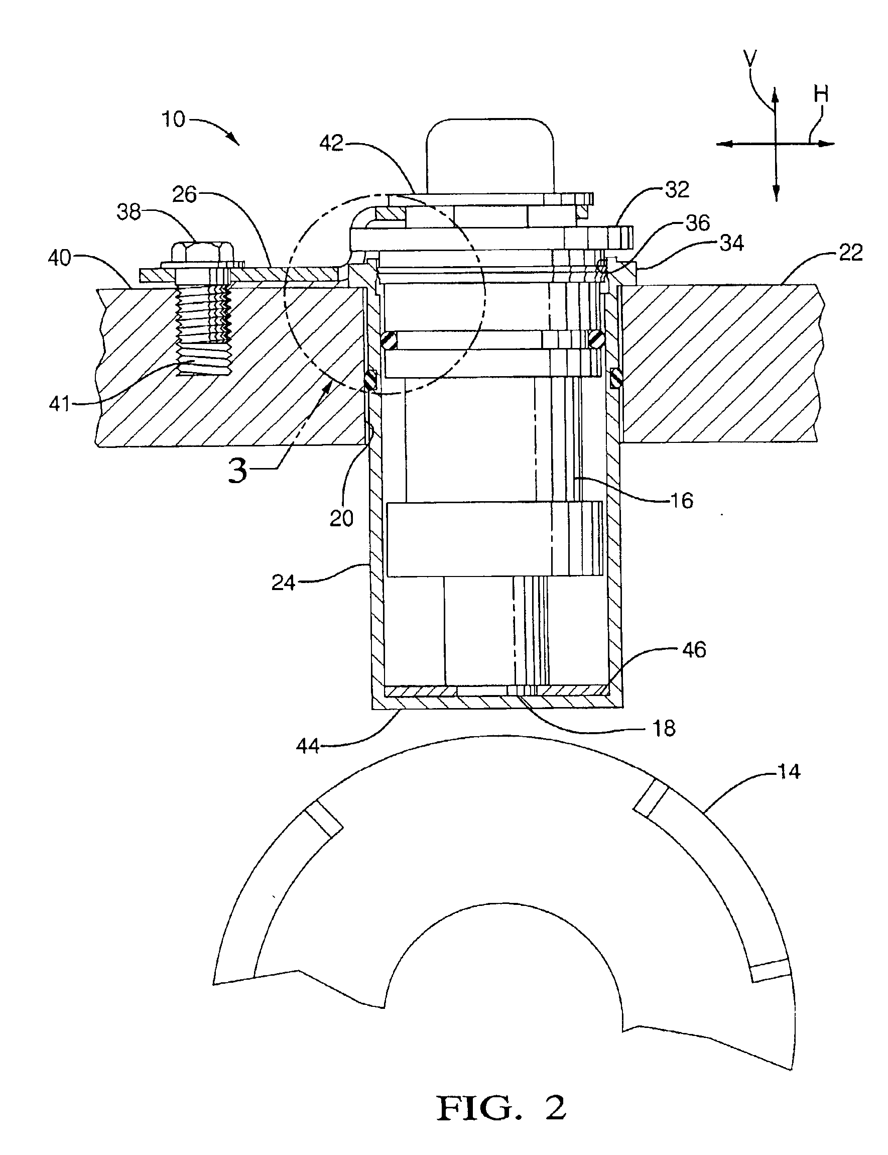
Referring now to the Drawings, FIGS. 1 and 2 generally depict an exemplary embodiment of a sensor probe bracket system 10 according to the present disclosure in an exemplar environment of operation, wherein the bracket system serves to locate a magnetic sensor 12 with respect to a reluctor 14. In this regard, the magnetic sensor 12 has a sensor body 16 which includes a sensor tip 18. The sensor tip 18 extends into a sensor bore 20 of an engine block 22, for example, via sensor housing 24 that is spaced from the reluctor 14 a predetermined distance equal to an optimum air gap G which provides optimal sensing performance by the magnetic sensor of magnetic field variations as the reluctor spins.

A sensor probe component bracket 26 (hereafter, simply “bracket”) of the sensor probe bracket system 10 is composed of a first bracket component 28 and a second bracket component 30 which lie substantially parallel with each other and are oriented parallel to a horizontal axis H and normal to th...


PUM


Abstract

A sensor package and method of making the same is disclosed in which the sensor package includes a sensor component for electromagnetic sensing having a sensor body with a sensor tip at one end. A sensor housing having a cavity for receiving the sensor component is disposed in a substrate and is aligned with an object to be sensed. The housing further includes a snap-fit interface with the sensor component that is configured to admit and secure the sensor tip during assembly thereof. A bracket is mechanically fixable to the substrate at a first end and is in operable communication with the sensor tip at a second end. The bracket is configured to bias the sensor tip towards the object to be sensed for elimination of an internal air gap between the sensor tip and housing formed during assembly thereof.

Description

TECHNICAL FIELDThe present disclosure relates to a method and apparatus for holding a first object with respect to a second object. More particularly, the present disclosure relates to a bracket system for precisely locating a sensor relative to an object to be sensed. Still more particularly, the present disclosure relates to a bracket system, wherein interaction between the bracket and the body of the sensor results in the sensor being fixed positionally with respect to the bracket, and further results in elimination of an internal air gap between the body of the sensor and a housing in which the sensor is disposed.BACKGROUND OF THE INVENTIONMagnetic sensors operate on the principle of detecting magnetic flux density modulation caused by the movement of appropriately configured reluctors (or targets). The magnetic sensor must be affixed very close to the reluctor since its sensitivity decreases very rapidly with the size of the air gap between the reluctor and the magnetic sensor....

Claims


Application Information

Patent Timeline
Patent Type & Authority Patents(United States)
IPC IPC(8): G01P1/02G01P3/488G01P1/00G01P3/42
CPCG01P1/00G01P3/488G01P1/026Y10T403/1616
Inventor SHOST, MARK ANTHONYCOLLINS, DUANE ZEDRICPALFENIER, SAMUEL ROLAND
Owner DELPHI TECH INC
Why Eureka
Try Eureka