
Antenna device

a technology of antennas and antennas, applied in the direction of resonant antennas, resonant antennas, independent non-interaction antenna combinations, etc., can solve the problems of excessive production capacity, increased production costs, plane-like structures, outward exposure, etc., to improve antenna characteristics and improve production efficiency.

Inactive Publication Date: 2014-08-21
MITSUBISHI STEEL MFG CO LTD
View PDF4 Cites 158 Cited by
  • Summary
  • Abstract
  • Description
  • Claims
  • Application Information

AI Technical Summary

Benefits of technology

This patent describes an antenna device that has a zigzag spring to expand and contract smoothly. The zigzag spring is held inside a space formed by two parts that hold the spring, which prevents the spring from buckling. The result is an improved production efficiency and improved antenna characteristics.

Problems solved by technology

However, in an antenna device formed such that the antenna element undergoes pattern formation on a conventional dielectric substrate and the antenna elements are laminated, there is a problem in that a production capacity becomes excessive and a production cost increases.
Further, in the conventional antenna device, the antenna element inevitably has a plane-like structure and is outwardly exposed.
Therefore, there is a problem in that good antenna characteristics are hardly obtainable.

Method used


Image

  • Antenna device
  • Antenna device
  • Antenna device

Examples


Embodiment Construction

[0022]Referring to figures, embodiments of the present invention are described.

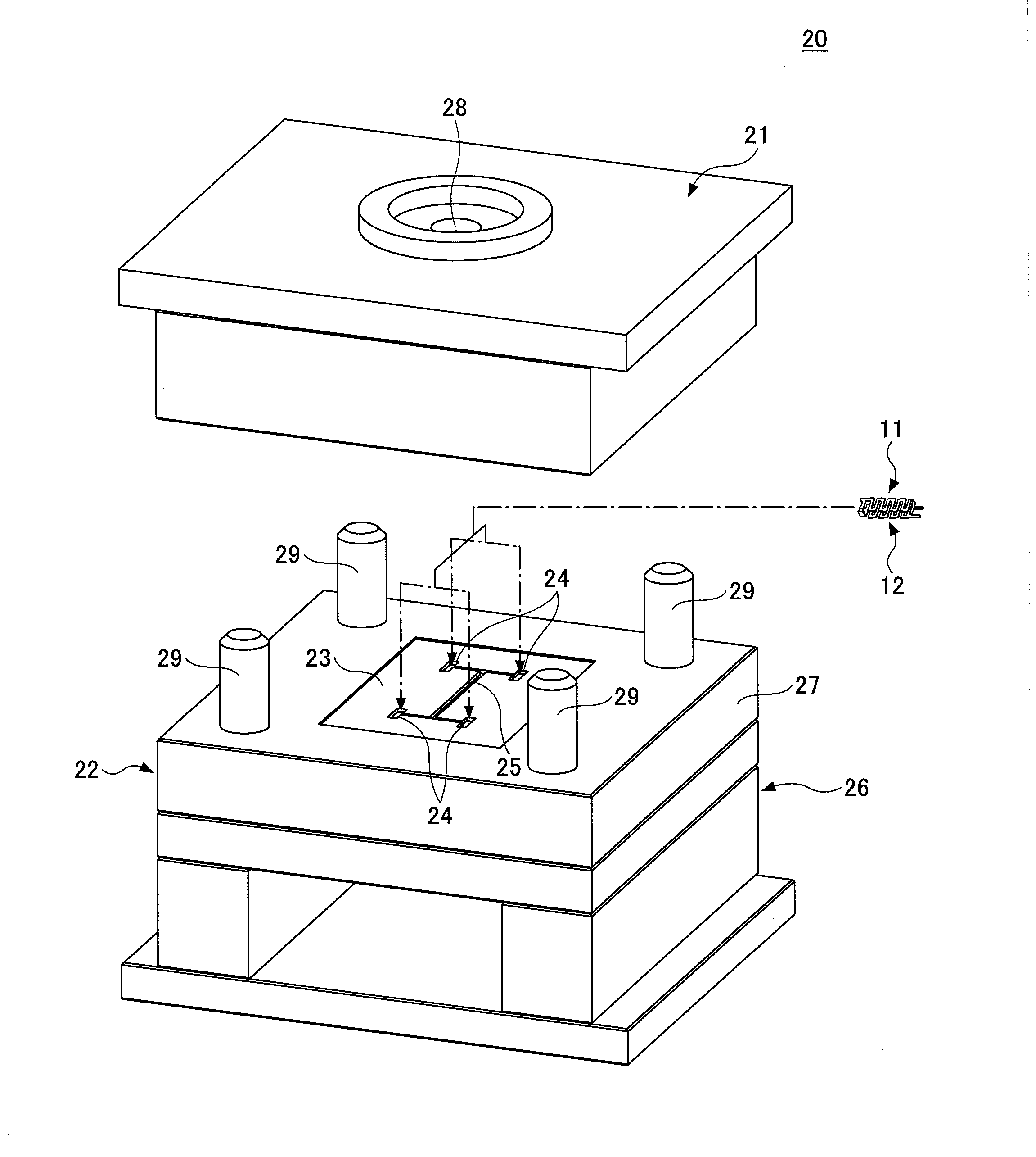
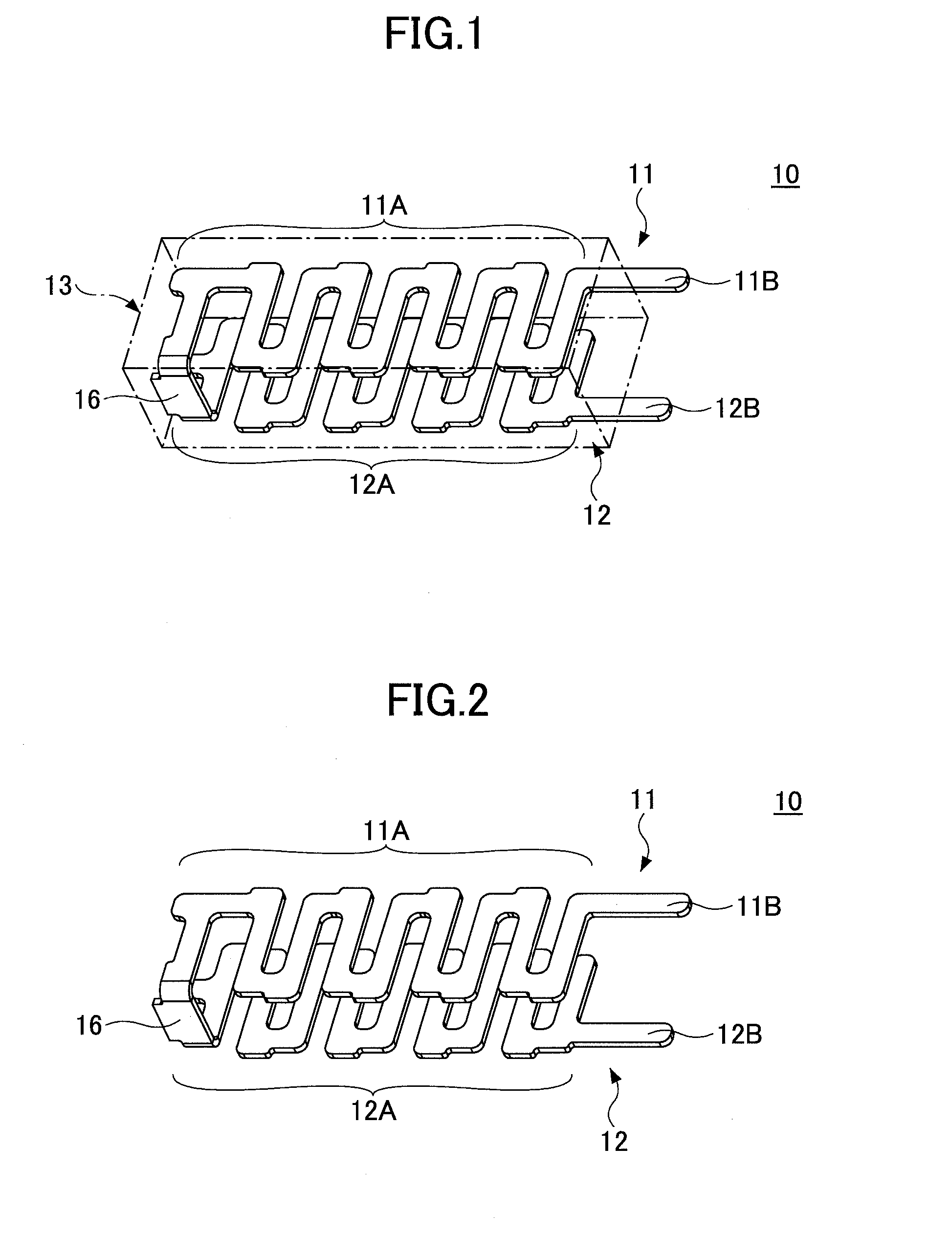
[0023]FIG. 1 illustrates an antenna device 10 as an embodiment of the present invention. The antenna device 10 of the embodiment is a double resonance antenna that is operated in two frequency bands. The antenna device 10 is installed in, for example, a portable terminal device such as a mobile phone or the like.

[0024]The antenna device 10 is formed by a first antenna element 11, a second antenna element 12, a sealing material 13, or the like.

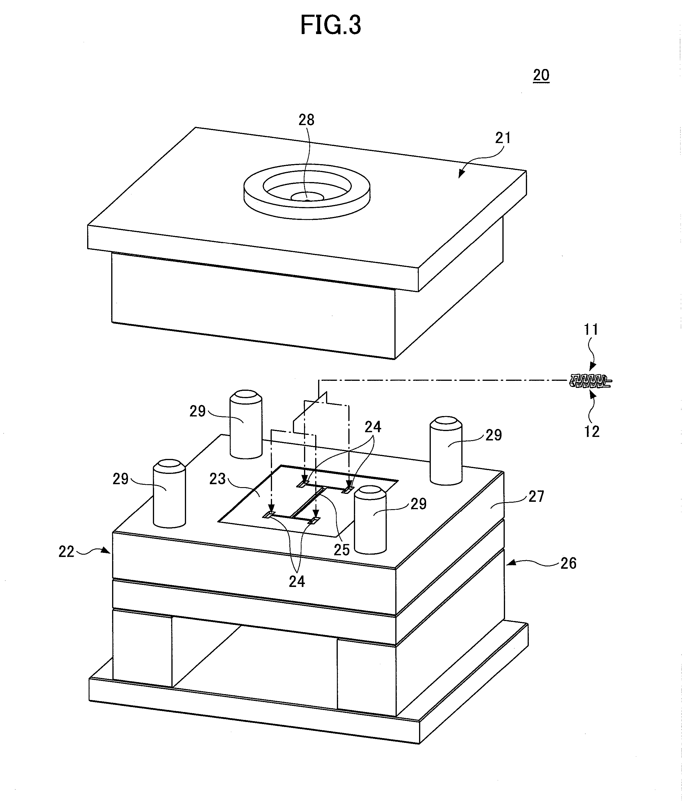
[0025]The first and second antenna elements 11 and 12 are integrally formed by press punching a conductive metallic plate. Within the embodiment, the first antenna element 11 positioned upward is a GPS antenna, and the second antenna 12 positioned downward is a Bluetooth antenna. The shapes of the first and second antenna elements 11 and 12 are the same. However, the shapes of the antenna elements 11 and 12 are not necessarily the same. As described later, it is poss...


PUM


Abstract

An antenna device includes a first antenna element made of a conductive metallic plate and formed in a shape of a meander; a second antenna element made of another conductive metallic plate and formed in another shape of a meander; and a sealing material which is made of a high-dielectric material and is configured to seal the first and second antenna elements by the sealing material, wherein the first antenna element is arranged in parallel with the second antenna element, and wherein the first and second antenna elements are embedded inside the sealing material by insert molding.

Description

TECHNICAL FIELD[0001]The present invention relates to an antenna device, particularly to an antenna device operable especially at two frequency bands.BACKGROUND ART[0002]In recent years, a portable terminal device typified by a mobile phone is equipped with various communication functions such as a global positioning system (GPS) function, a Bluetooth function, a wireless LAN function, or the like. Communications between various electronic apparatuses are enabled by the functions. An antenna for communications is built into such a portable terminal device. In a portable terminal device having a plurality of communication functions (e.g., two communication functions), two antennas corresponding to these functions are provided. On the other hand, the portable terminal device is required to be thin or compact. Because space efficiency is lowered by individually providing the two antennas, there is proposed an antenna in which the two antennas are integrated (see Patent Document 1).[000...

Claims


Application Information

Patent Timeline
IPC IPC(8): H01Q1/40
CPCH01Q1/40H01Q1/36H01Q7/00H01Q21/28H01Q1/243H01Q9/42H01Q5/378
Inventor SHIGEMOTO, YOKOHIROSE, EIJIISHIDA, TOMOYA
Owner MITSUBISHI STEEL MFG CO LTD
Learn More