Multi-carrier integration apparatus for distributed antenna system

a distributed antenna and integrated technology, applied in electrical apparatus, wireless communication services, wireless commuication services, etc., can solve the problems limiting the use of a das to a single carrier, and reducing the efficiency of resource efficiency and cost efficiency, so as to enhance efficiency and reduce the cost of operation. , the effect of increasing the initial investment cost of the system

Active Publication Date: 2014-08-21
ADVANCED RF TECH
View PDF7 Cites 30 Cited by
  • Summary
  • Abstract
  • Description
  • Claims
  • Application Information

AI Technical Summary

Benefits of technology

[0009]Embodiments of the present invention are directed to an apparatus to connect BTS or BDA with a DAS by integrating or distributing multiple carrier signals. To be more specific, to accommodate one or more additional carriers after installation of a DAS for a specific sin...

Problems solved by technology

Meanwhile, limiting use of a DAS to a single carrier may be less desirable in, for example, the aspects of resource efficiency and cost efficiency.
This ...

Method used


Image

  • Multi-carrier integration apparatus for distributed antenna system
  • Multi-carrier integration apparatus for distributed antenna system
  • Multi-carrier integration apparatus for distributed antenna system

Examples


Embodiment Construction

[0023]With reference to the attached drawings, exemplary embodiments for implementing the present invention will be described in detail below. Similar features may be represented by the same or similar reference numbers.

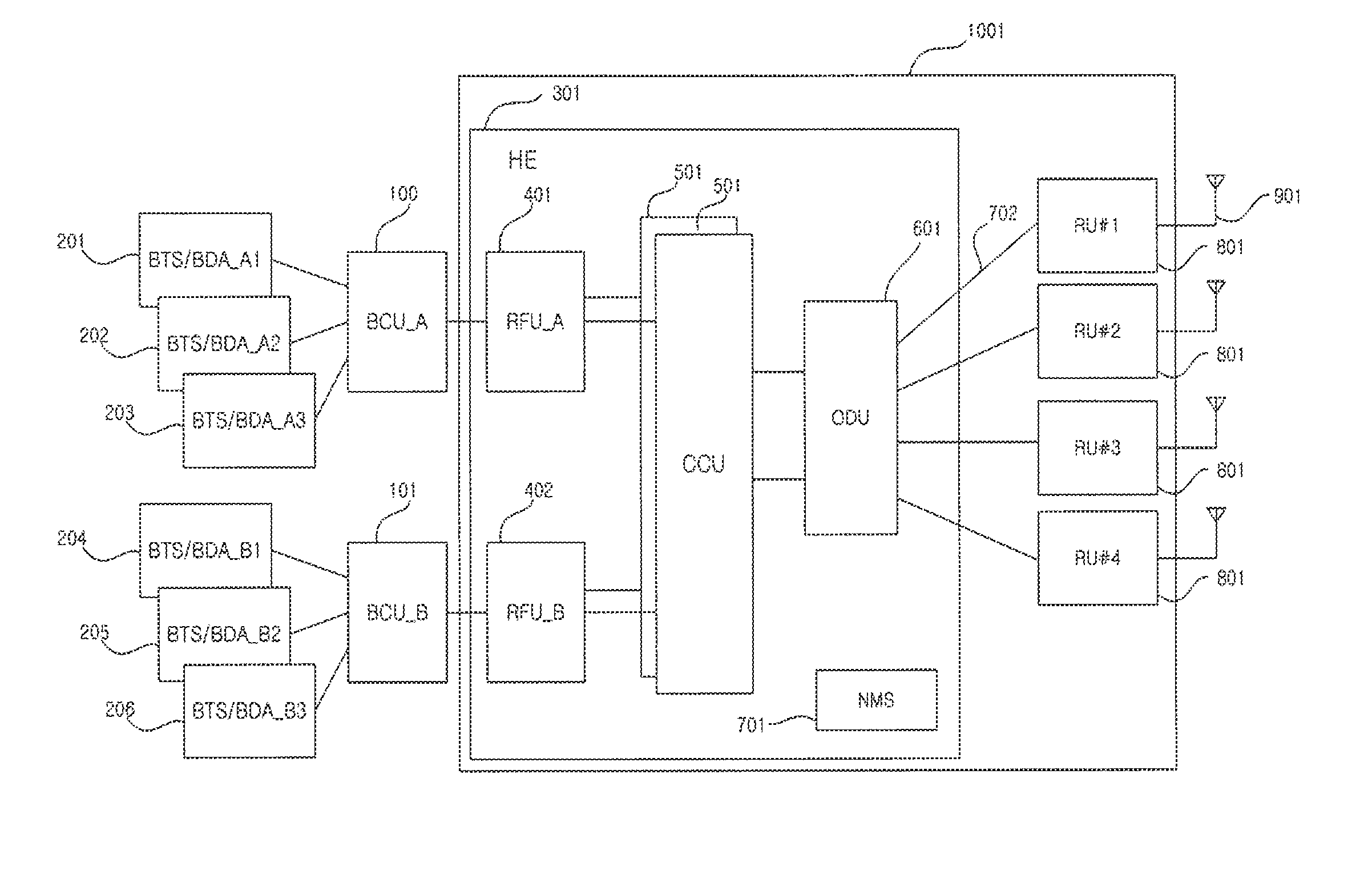
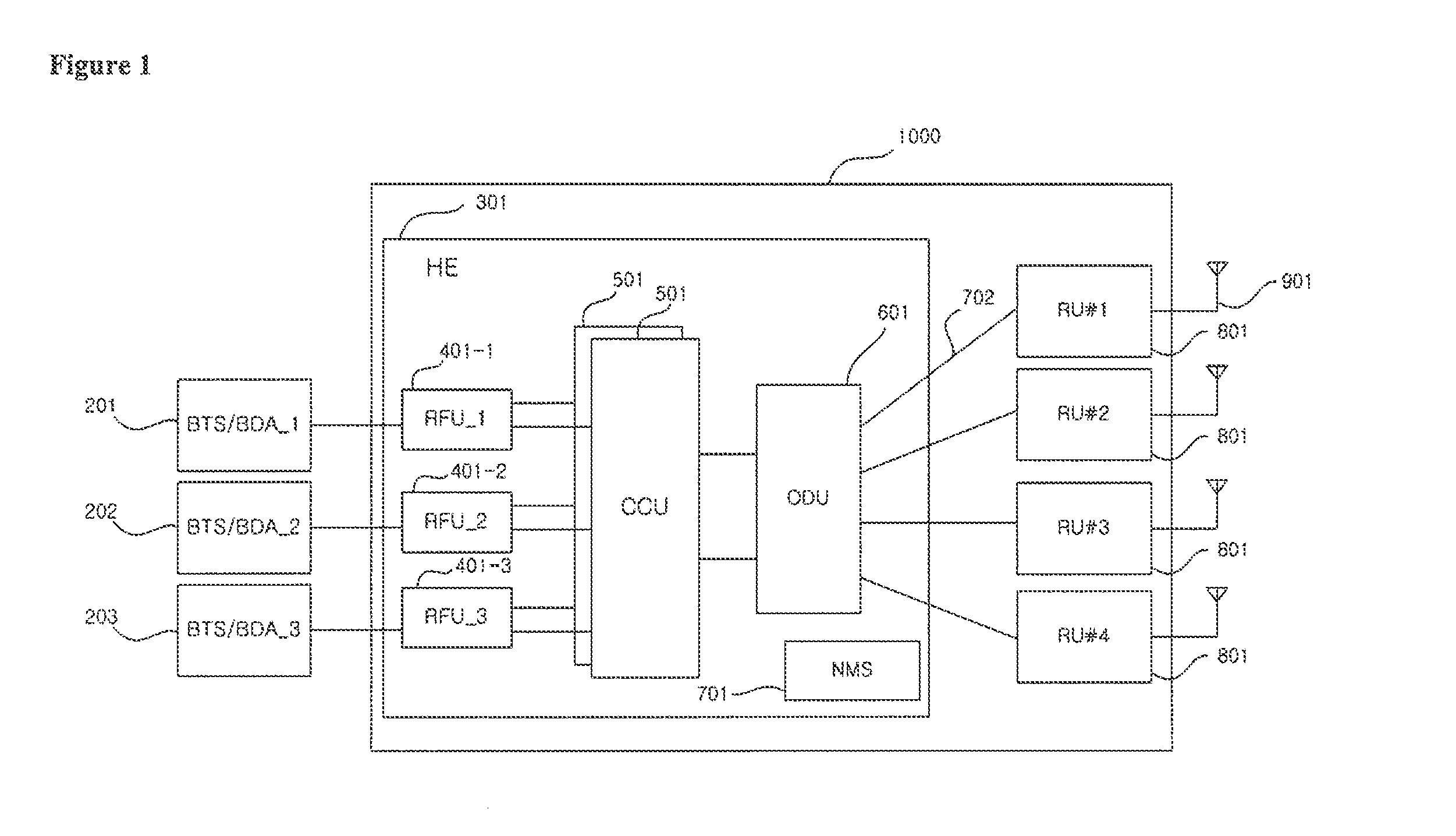
[0024]FIG. 1 shows a general configuration of a distributed antenna system (DAS) with a separate RF Unit (RFU) for each carrier, respectively, where the system supports three carriers.

[0025]In FIG. 1, the DAS (1000) includes a head end (HE) 301 and remote units (RU) 801, where a separate RFU (401-1, 401-2, 401-3) is assigned for each carrier, and RF interfaces with Base Transceiver Stations / Bi-directional Amplifiers (BTS / BDA) 201, 202, 203 for each respective carrier. The HE (301) is connected with the RUs (801) through optic lines, where the system expands into multiple RU's 801 through optic expansion. Each RU (801) is connected to the HE (301) via an optic core line (702), and transmits signals to, and / or receives signals from, for example, a Mobile Station (not s...


PUM


Abstract

A band combiner unit includes a plurality of carrier modules (CMs) each configured to be connected to a base transceiver station (BTS) or bi-directional amplifier (BDA) for corresponding ones of the carriers, wherein each of the CMs is configured to transmit downlink signals from the corresponding BTS/BDA, adjust the downlink signals, and transmit the downlink signals to a first combiner, and to receive uplink signals from a second combiner, adjust the uplink signals, and transmit the uplink signals to the corresponding BTS/BDA, the first combiner configured to combine the downlink signals from the CMs, and transmit the combined downlink signals to a distributed antenna system (DAS), the second combiner configured to split a combined uplink signal from a DAS, and transmit the split uplink signals to corresponding ones of the CMs, and a band combiner unit controller for monitoring and controlling the CMs.

Description

CROSS-REFERENCE TO RELATED APPLICATION(S)[0001]The present application claims priority to and the benefit of U.S. Provisional Patent Application Ser. No. 61 / 767,179, filed Feb. 20, 2013, the contents of which are hereby incorporated by reference in their entirety.BACKGROUND[0002]1. Field of the Invention[0003]Embodiments of the present invention is related to an apparatus for a distributed antenna system (DAS), and more specifically, to a multi-carrier integration unit or band combiner unit (BCU) for a DAS, to facilitate more efficient multi-carrier service.[0004]2. Description of Related Art[0005]Distributed antenna systems (DAS) are utilized to provide more stable wireless mobile telecommunications services inside buildings, such as large stadiums, hospitals, hotels, campuses, etc. With an increasing number of mobile communication subscribers, the number of bands and carriers (e.g., wireless service providers) are also increasing. In view of this, support of multiple bands, as wel...

Claims


Application Information

Patent Timeline
IPC IPC(8): H04W88/08
CPCH04W88/08H04W88/085
Inventor KO, YOUNG-HOON
Owner ADVANCED RF TECH
Why Eureka
Try Eureka