
Method and apparatus to determine time and distance between transceivers using phase measurements

a technology of phase measurement and transceiver, which is applied in the direction of synchronisation arrangement, transmission monitoring, instruments, etc., can solve the problems of high uncertainty in position estimation and inability to determine when a signal is received

Inactive Publication Date: 2014-08-21
QUALCOMM INC
View PDF1 Cites 10 Cited by
  • Summary
  • Abstract
  • Description
  • Claims
  • Application Information

AI Technical Summary

Benefits of technology

The patent describes a method and apparatus for estimating the time it takes for a signal to travel between two points in an orthogonal frequency division multiplexing (OFDM) system. This is useful for determining the distance between the two points and the speed of the signal in the system. The method involves transmitting a signal in a window and receiving it in another window, with the difference in time between the two windows being measured. The apparatus includes a transceiver and a processor for performing the method. The technical effect of this patent is to provide a more accurate and reliable way to estimate the time it takes for a signal to travel between two points in an OFDM system.

Problems solved by technology

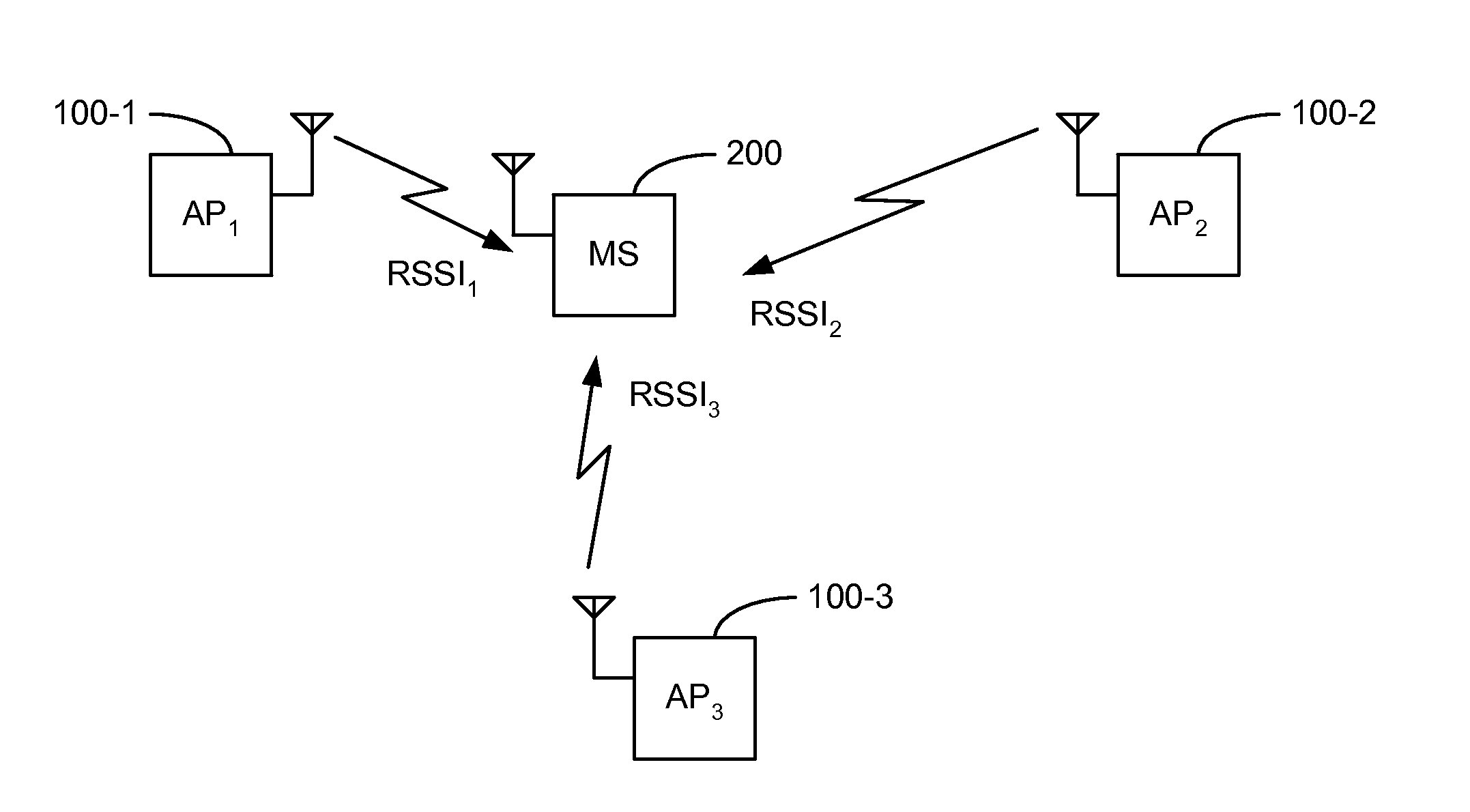
Unfortunately, trilateration with RSSI measurements results in a high level of uncertainty in position estimation because of the uncertainty of the RSSI measurement themselves and dependency on an accurate distance model based on RSSI measurements.
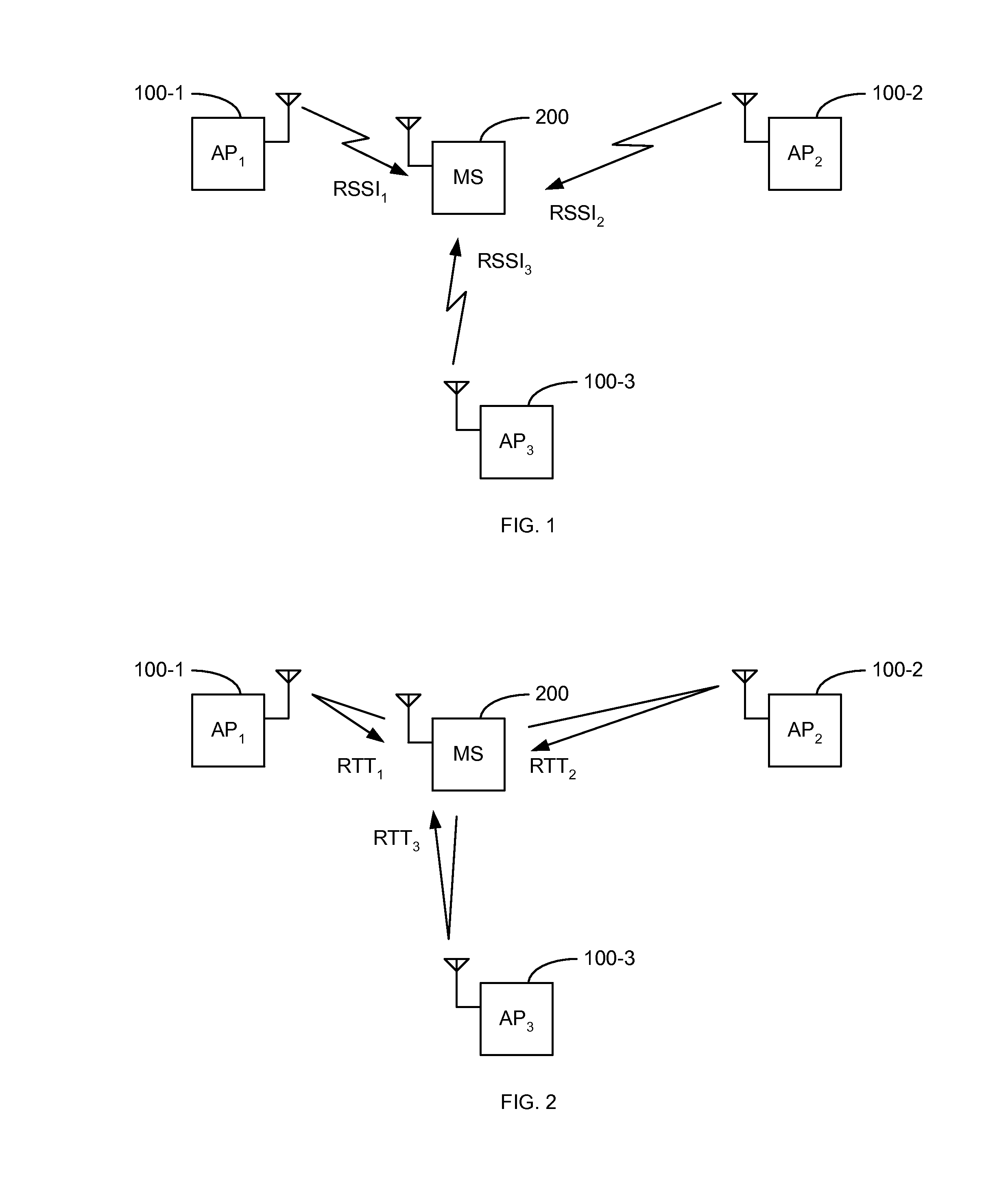
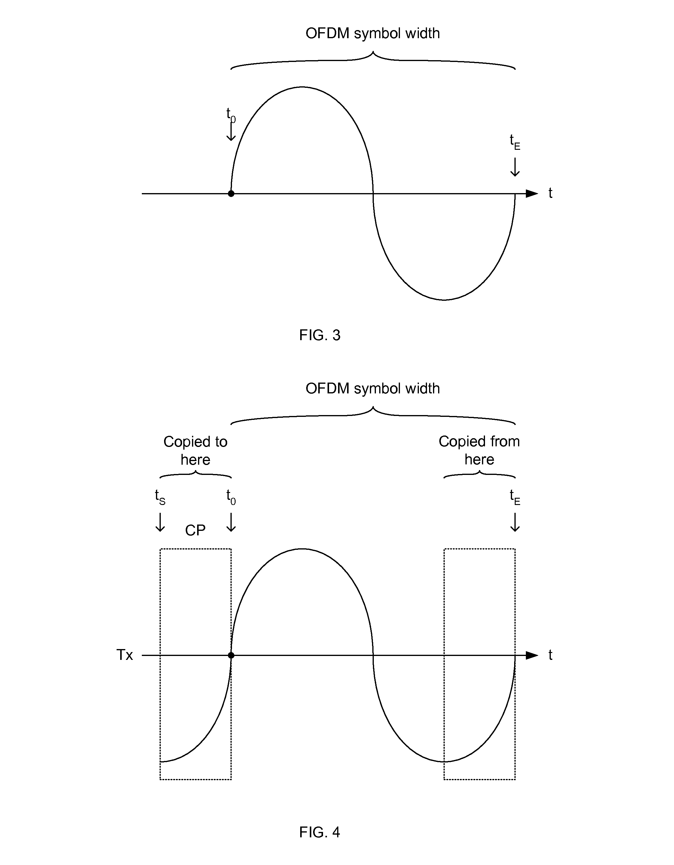
Unfortunately, determining when a signal is received may be inaccurate up to 20% or 25% of a width of an OFDM symbol, therefore, other means are used to determine RTT.

Method used


Image

  • Method and apparatus to determine time and distance between transceivers using phase measurements
  • Method and apparatus to determine time and distance between transceivers using phase measurements
  • Method and apparatus to determine time and distance between transceivers using phase measurements

Examples


Embodiment Construction

[0038]The detailed description set forth below in connection with the appended drawings is intended as a description of various aspects of the present disclosure and is not intended to represent the only aspects in which the present disclosure may be practiced. Each aspect described in this disclosure is provided merely as an example or illustration of the present disclosure, and should not necessarily be construed as preferred or advantageous over other aspects. The detailed description includes specific details for the purpose of providing a thorough understanding of the present disclosure. However, it will be apparent to those skilled in the art that the present disclosure may be practiced without these specific details. In some instances, well-known structures and devices are shown in block diagram form in order to avoid obscuring the concepts of the present disclosure. Acronyms and other descriptive terminology may be used merely for convenience and clarity and are not intended...


PUM


Abstract

Systems, apparatuses and methods are disclosed for estimating a signal travel time, and thus distance between transceivers, in an orthogonal frequency division multiplexing (OFDM) system. The signal travel time is measured between a transmit time (tT) and a receive window time (twindow) adjusted by the phase delay (TΦ). The phase delay (TΦ) is determined as a difference between a receive time (tR) and the receive window time (twindow). The receive time (tR) may be determined based on either an amplitude of the received signal at the receive window time (twindow) or when the received signal crosses a positive-negative axis. In synchronous systems, either a one-way time (OWT) or round-trip time (RTT) may be used for estimation. In asynchronous systems, an RTT is used for estimation.

Description

BACKGROUND[0001]I. Field of the Invention[0002]This disclosure relates generally to apparatus and methods for position estimation of a wireless device, and more particularly to determining a time of arrival in RTT (round-trip time) systems or OWT (one way time) if the systems are synchronous.[0003]II. Background[0004]To assist in position estimation, a mobile device may capture received signal strength indication (RSSI) measurements from three or more access points. A server or the mobile device itself may apply trilateration to these RSSI measurements using a distance model based on RSSI to estimate a position of the mobile device. Unfortunately, trilateration with RSSI measurements results in a high level of uncertainty in position estimation because of the uncertainty of the RSSI measurement themselves and dependency on an accurate distance model based on RSSI measurements.[0005]Round-trip time (RTT) or one way time (OWT) measurements advantageously have a much lower level of dis...

Claims


Application Information

Patent Timeline
IPC IPC(8): H04W24/00
CPCH04W24/00H04L43/0864G01S5/14H04L43/0858H04L27/2662H04W56/00H04J3/0682H04L27/2665
Inventor PON, RAYMAN WAIFARMER, DOMINIC GERARD
Owner QUALCOMM INC
Learn More