Shaft with a Flange Connection

Inactive Publication Date: 2014-08-21
KHD HUMBOLDT WEDAG GMBH
View PDF21 Cites 4 Cited by
  • Summary
  • Abstract
  • Description
  • Claims
  • Application Information

AI Technical Summary

Benefits of technology

[0014]Since, according to the invention, the diameter of the flange is not greater than the widest region of the shaft, the flange plates also must not be too wide. However, a comparatively small flange results correspondingly in a relatively small contact area of the flange plates. As a consequence, the torque during the rotation of the shaft is transmitted to a relatively small area of the flange. It is therefore provided in one advantageous embodiment of the invention to insert one or more friction disks having a high

Problems solved by technology

This in turn has the disadvantage that the machine elements which are arranged on the shaft can then no longer be readily removed at the hub along the shaft, since they then no longer fit through the wider flange, which presents a great obstacle, for example, when replacing rolls or the antifriction bearings i

Method used


Image

  • Shaft with a Flange Connection
  • Shaft with a Flange Connection

Examples


Embodiment Construction

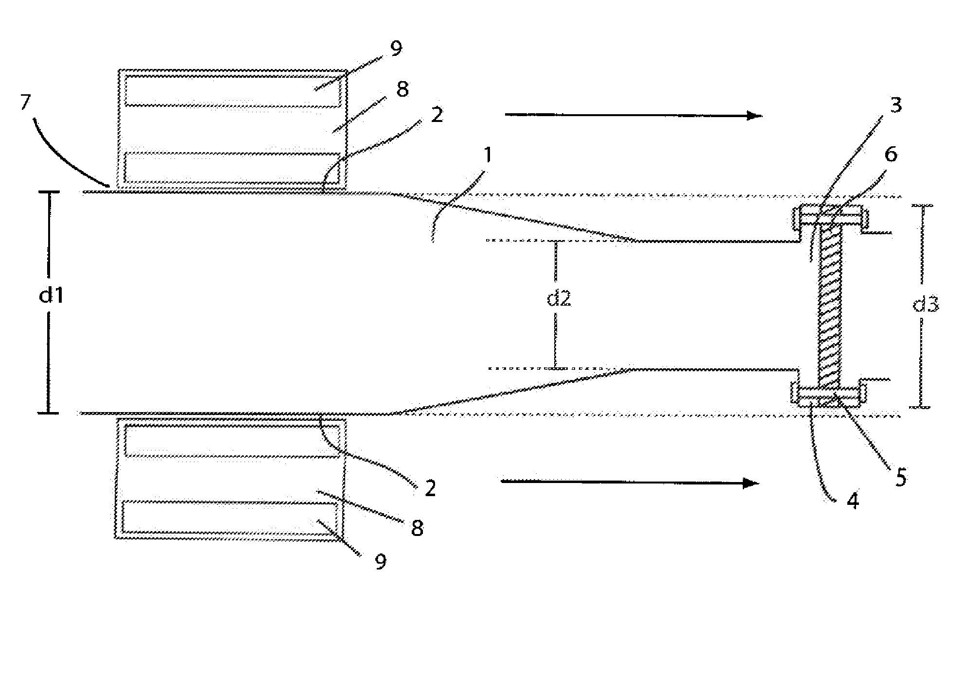
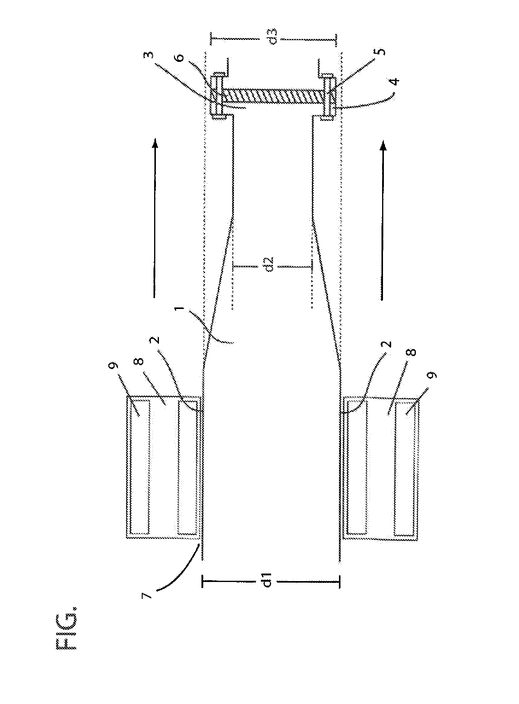
[0019]The FIGURE shows a shaft 1 which has a diameter d1 at the location of the antifriction bearing seat 2. The shaft 1 tapers conically in the direction of the flange 3 and has a diameter d2 in the narrower region. The flange 3 is situated with the flange plates 4 at the narrower end of the shaft 1 with a diameter d3, which flange 3 is forged on the shaft 1 in this example and is therefore in one piece with the shaft. The flange plate 4 of one shaft 1 is connected to the flange plate 4 of an abutting shaft 1 by screws 5. In order to transmit the torque, a friction disk 6 is attached between the flanges 3, which friction disk 6 ensures that the forces which are caused by the rotation are distributed homogeneously on the flange plates 4. On the wider end of the shaft 1, an antifriction bearing 8 with the rolling bodies 9 which are situated therein is attached at the hub 7. The diameter d3 of the flange connection 3 is somewhat smaller than the inner diameter d1, on which the antifri...


PUM


Abstract

A flange connection on a shaft having at least two diameters of different size, wherein the diameter of the flange connection is smaller than a diameter of the roller bearing seat. Machine parts on the shaft can thereby be rapidly and simply interchanged without the flange having to be removed in the process.

Description

CROSS-REFERENCES TO RELATED APPLICATIONS[0001]This application claims the benefit of the German patent application No. 202011106443.7 filed on Sep. 28, 2011, the entire disclosures of which are incorporated herein by way of reference.BACKGROUND OF THE INVENTION[0002]The invention relates to a flange connection on a shaft, which flange connection makes it possible to replace machine parts on the shaft rapidly and simply, without the flange having to be removed in the process.[0003]Flange is generally used to denote an attachment to components such as pipes, shafts or housings, which attachment serves to connect or to couple the respective component to another element. A characteristic of the flange is the flange plates which surround the elements in a circularly annular manner at their connecting point and by way of which the flange is connected by pressing onto one another. The connection can be of irreversible design, for example by welding of the flange plates, or else of reversib...

Claims


Application Information

Patent Timeline
IPC IPC(8): F16D1/02
CPCF16D1/02B02C4/28B30B3/00F16C3/02F16C13/00F16D1/027F16D1/033F16B2200/50
Inventor FRANGENBERG, MEINHARD
Owner KHD HUMBOLDT WEDAG GMBH
Why Eureka
Try Eureka