Air contaminant system with laminar flow

a laminar flow and air contaminant technology, applied in ventilation systems, heating types, stoves or ranges, etc., can solve the problems of contaminants drawn into a closed container, workers within the unit exposed to any contaminants that are generated, and complex systems that filter contaminants

Active Publication Date: 2014-08-21
DUROAIR TECH
View PDF25 Cites 20 Cited by
  • Summary
  • Abstract
  • Description
  • Claims
  • Application Information

AI Technical Summary

Benefits of technology

[0013]A third object of the invention is to disclose an airborne ...

Problems solved by technology

In other cases, complex systems filter contaminants which are then expelled through ducts or stacks to the outside of the environment.
These solutions are often expensive and require permanent locations, thus requiring the movement of the items (“work pieces”) to be cleaned or otherwise treated to be moved to a separate cleaning facility.
However, workers within the unit are exposed to any contaminants t...

Method used


Image

  • Air contaminant system with laminar flow
  • Air contaminant system with laminar flow
  • Air contaminant system with laminar flow

Examples


Embodiment Construction

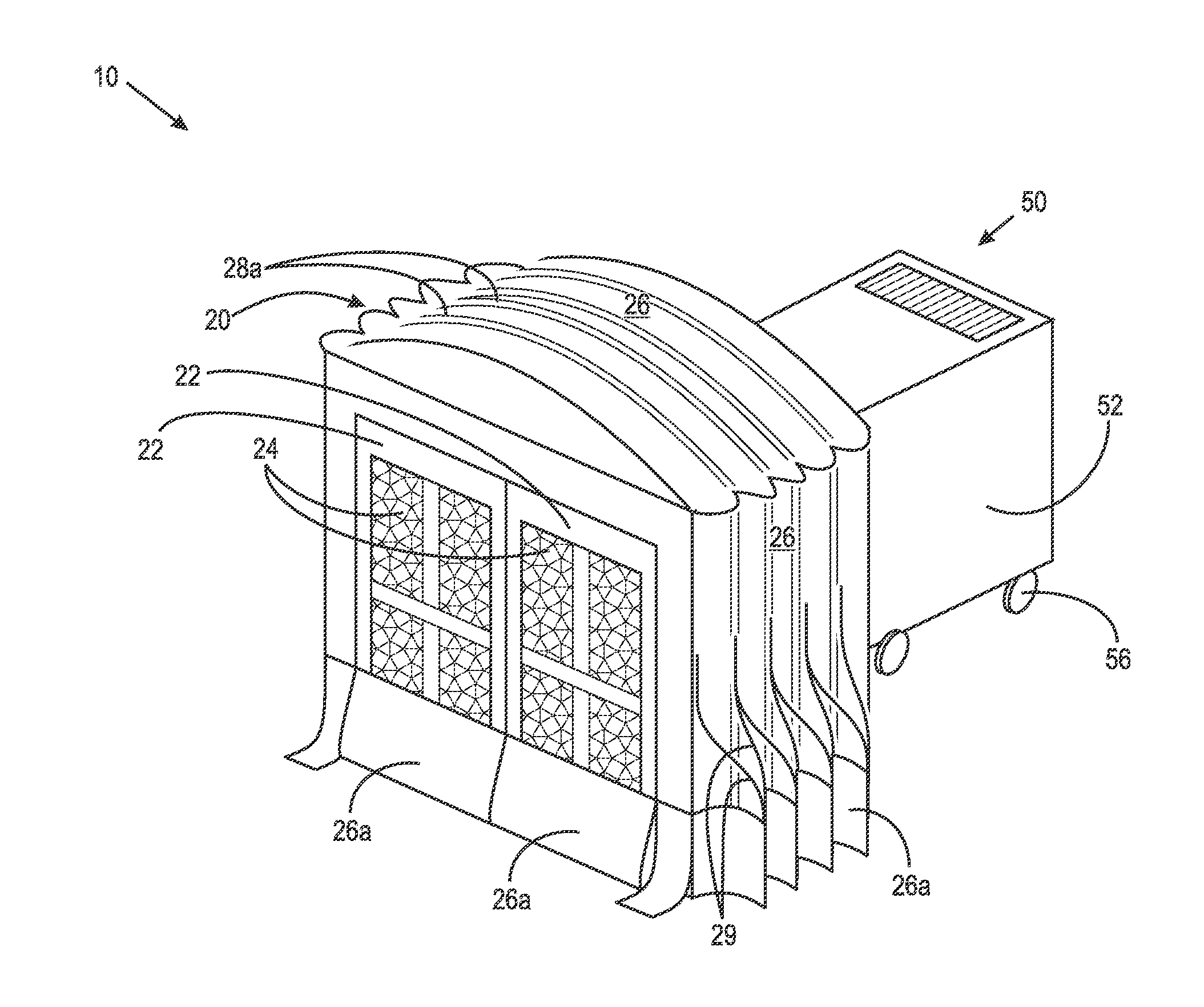
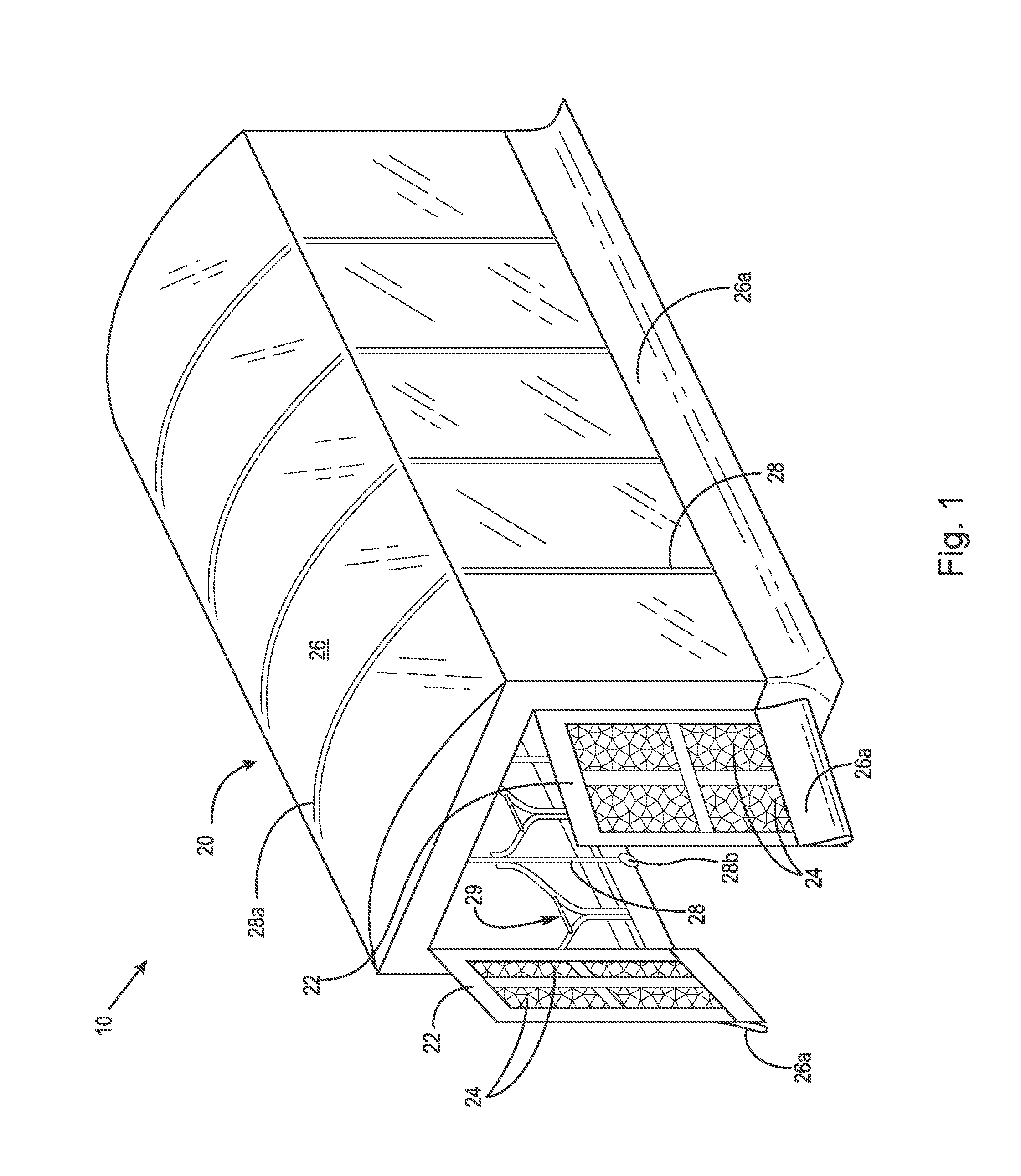
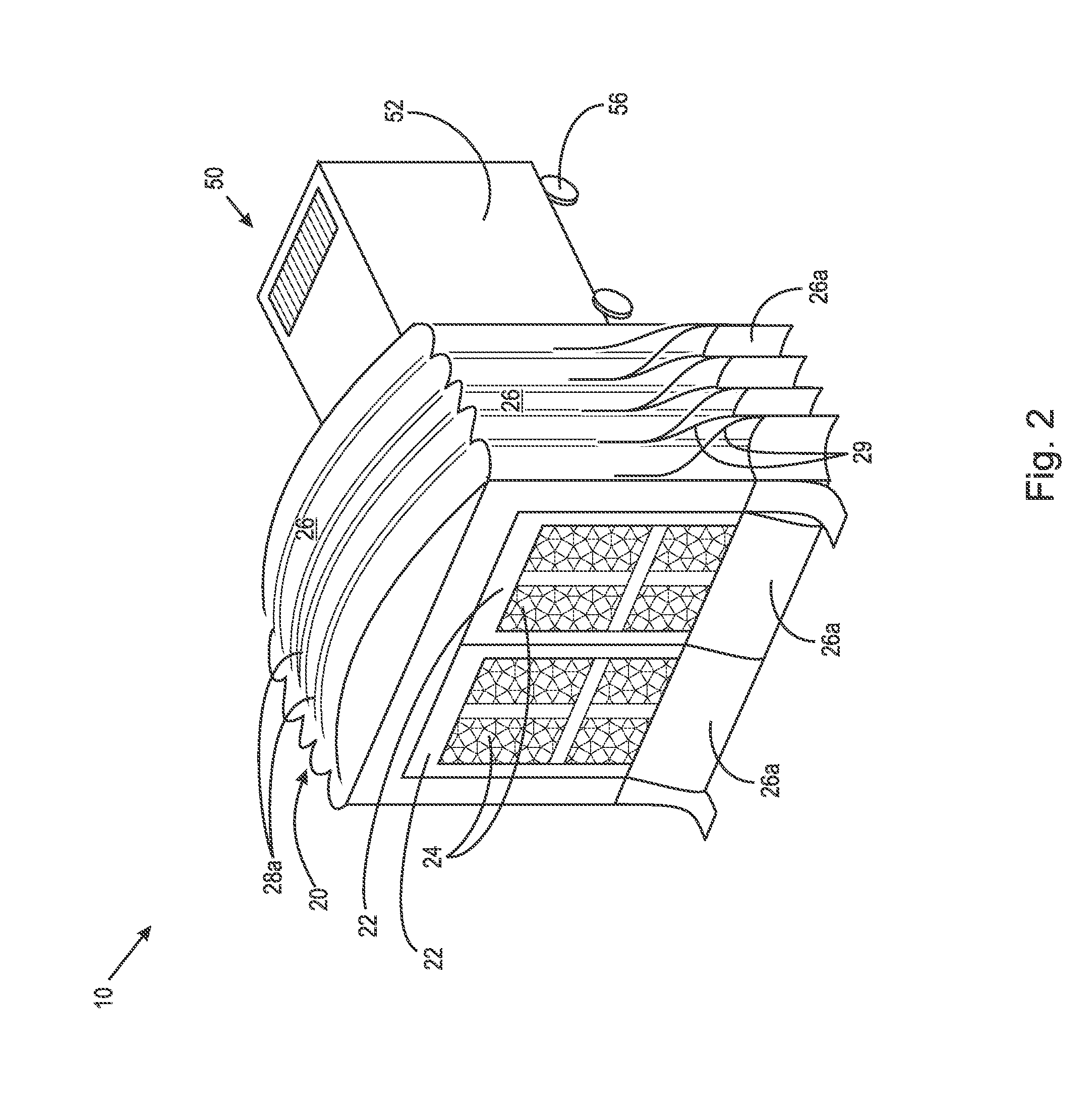
[0024]At the outset, it should be appreciated that like drawing numbers on different drawing views identify identical structural elements of the invention. It also should be appreciated that figure proportions and angles are not always to scale in order to clearly portray the attributes of the present invention.

[0025]While the present invention is described with respect to what is presently considered to be the preferred embodiments, it is understood that the invention is not limited to the disclosed embodiments. The present invention is intended to cover various modifications and equivalent arrangements included within the spirit and scope of the appended claims.

[0026]Furthermore, it is understood that this invention is not limited to the particular methodology, materials and modifications described and as such may, of course, vary. It is also understood that the terminology used herein is for the purpose of describing particular aspects only, and is not intended to limit the scope...


PUM


Abstract

The present invention is directed toward a movable airborne contaminant control system having a retractable/extendable booth attached in a sealing manner to a ventilation unit, preferably mounted on wheels. The ventilation unit includes a filter assembly that opens into the work are formed by the booth. Front doors support air filters. In operation, the ventilation unit draws air in a longitudinal laminar flow over one or more work pieces. The filter assembly captures both particulates and VOCs to allow the exhaust air to include an extremely low contaminant load.

Description

FIELD OF THE INVENTION[0001]The present invention pertains to devices for controlling airborne contaminants, specifically to contaminants generated during servicing operations within a building, and more specifically to containment of airborne contaminants generated within an enclosed environment.BACKGROUND OF THE INVENTION[0002]The generation of airborne contaminants generated during cleaning, coating, refurbishing and similar operations is often accompanied by the necessity of controlling the contaminants to reduce or eliminate damage to the environment and to not compromise the safety of workers operating in the operational environment. Often these needs are met by the construction of complex systems that filter or divert contaminants to waste collection points for removal offsite. In other cases, complex systems filter contaminants which are then expelled through ducts or stacks to the outside of the environment. In some situations, operations are required to be performed outsid...

Claims


Application Information

Patent Timeline
IPC IPC(8): B08B15/02F24F1/035F24F1/0353F24F1/0355F24F8/108F24F8/158
CPCB08B15/02E04H15/14E04H15/52F24F1/02F24F3/1603F24F11/085E04H1/1277F24F11/30B05B16/60B05B14/43B05B16/40B05B16/80F24F8/10F24F1/0355F24F1/035F24F1/0353F24F8/108F24F8/158
Inventor RANKIN, KELLY
Owner DUROAIR TECH
Why Eureka
Try Eureka