Device for a syringe
- Summary
- Abstract
- Description
- Claims
- Application Information
AI Technical Summary
Benefits of technology
Problems solved by technology
Method used
Image
Examples
Embodiment Construction
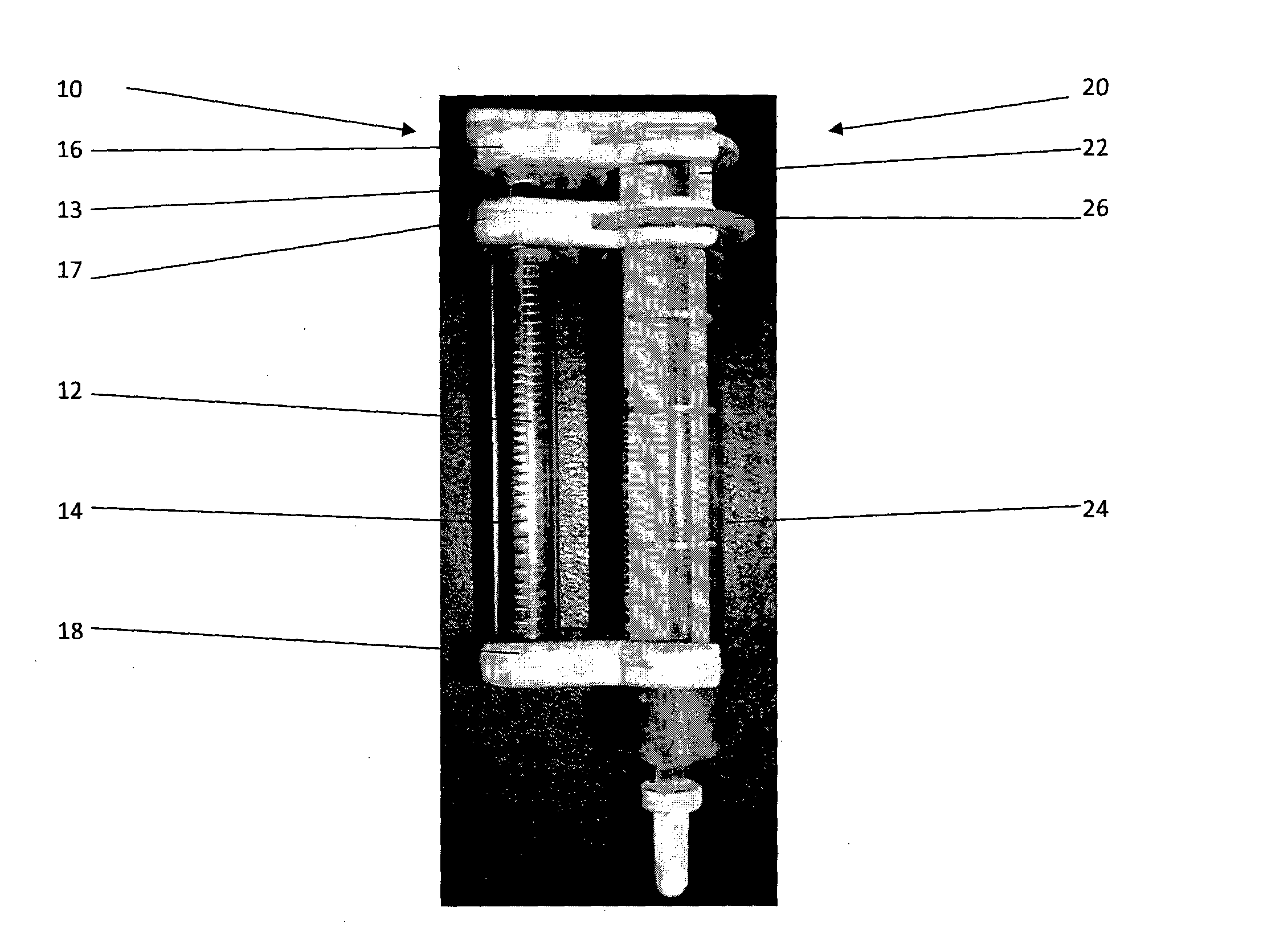
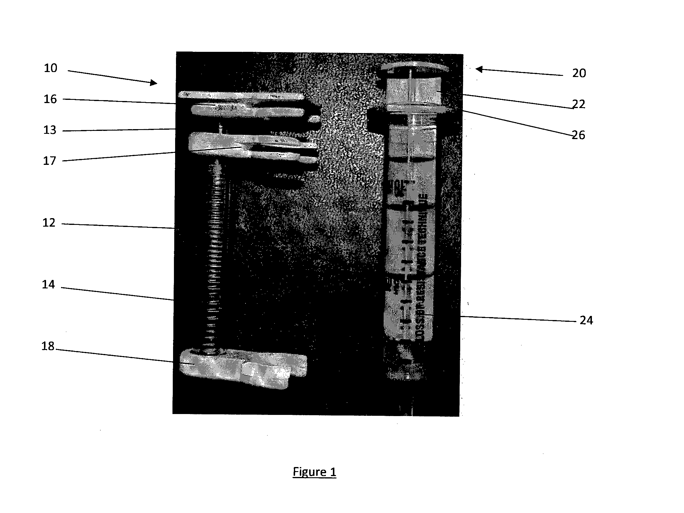
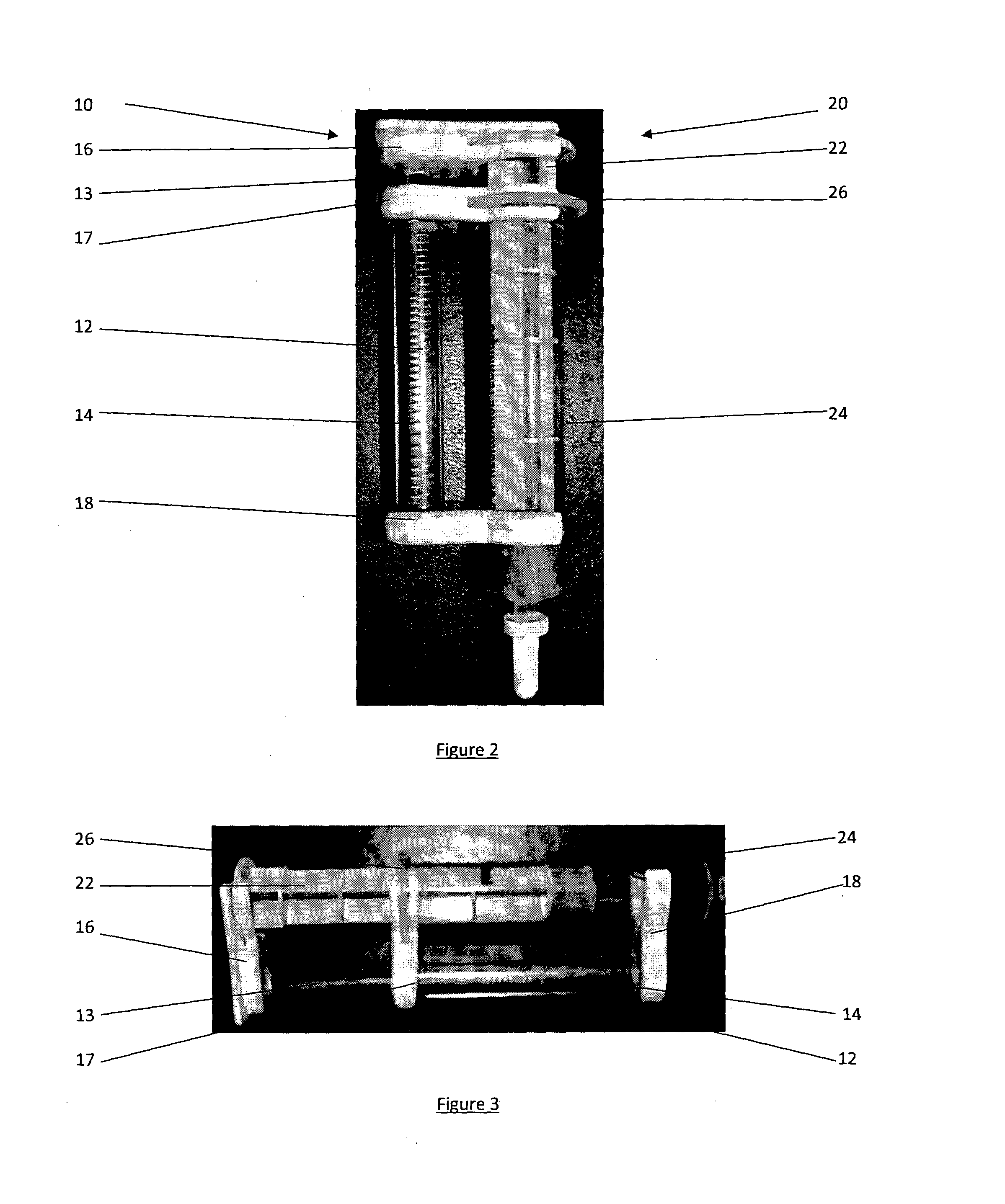
[0026]Referring to FIGS. 1, 2 and 3 in which like features of the invention are indicated by like numerals.
[0027]An accessory 10 for a Loss or Resistance Syringe 20 is disclosed. The syringe 20 has a plunger 22 slidably located in a barrel 24. The accessory 10 comprises a coiled spring 12, located on a shaft 13, enclosed in a housing 14 and attachable to the exterior of the syringe 20.
[0028]Clip 16 is located at the head of the shaft 13, and attaches the shaft 13 to the plunger 22 of the syringe 20. Clip 17 is located at the top end of the housing 14, and attaches the housing to the top of the barrel 24 of the syringe 20—either just below or around the flange 26 of the barrel 24. Clip 18 attaches the housing 14 at a further point along the barrel 24 of the syringe 20.
[0029]In use, and referring to FIG. 3, when the plunger 22 of the syringe 20 is withdrawn, the shaft 13 of the accessory 10 is withdrawn from the housing 14 of the accessory 10. This in turn causes the spring 12 to be s...
PUM
 Abstract
Description
Claims
Application Information
 - R&D
- Intellectual Property
- Life Sciences
- Materials
- Tech Scout
- Unparalleled Data Quality
- Higher Quality Content
- 60% Fewer Hallucinations
Browse by: Latest US Patents, China's latest patents, Technical Efficacy Thesaurus, Application Domain, Technology Topic, Popular Technical Reports.
© 2025 PatSnap. All rights reserved.Legal|Privacy policy|Modern Slavery Act Transparency Statement|Sitemap|About US| Contact US: help@patsnap.com


