Tubular oil cooler

An oil cooler and tube-and-tube technology, which is applied in the direction of engine components, engine lubrication, lubricating parts, etc., can solve the problems of large loss of liquid flow resistance, low heat exchange efficiency, short service life, etc. Loss of flow resistance, extended life, and improved reliability

Inactive Publication Date: 2014-02-12
常州市华立液压润滑设备有限公司
View PDF0 Cites 0 Cited by
  • Summary
  • Abstract
  • Description
  • Claims
  • Application Information

AI Technical Summary

Problems solved by technology

[0003] In order to overcome the disadvantages of low heat transfer efficiency, large liquid flow resistance loss, low heat dissipat...

Method used


Image

  • Tubular oil cooler

Examples


Embodiment Construction

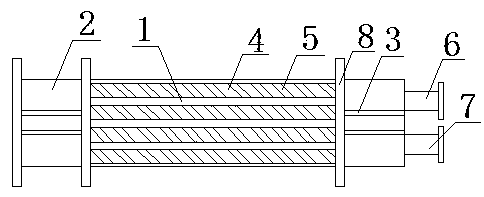
[0010] Such as figure 1 It is a structural schematic diagram of the present invention, a tube-and-tube oil cooler, including a tube body 1, an oil chamber 2, a flow partition 3, a heat dissipation circular tube 4, a spoiler 5, an oil inlet pipe 6, an oil outlet pipe 7 and a tube plate 8. There are oil chambers 2 on both sides of the pipe body 1, the oil chamber 2 is provided with a flow divider 3, the pipe body 1 is provided with a heat dissipation circular tube 4, and the heat dissipation circular pipe 4 is provided with a spoiler 5, and the pipe body 1 An oil inlet pipe 6 and an oil outlet pipe 7 are arranged outside the oil chamber 2 on the right side, and a tube plate 8 is arranged between the pipe body 1 and the oil chamber 2 .

[0011] When in use, both sides of the pipe body 1 are connected to the oil chamber 2, a tube plate 8 is provided between the pipe body 1 and the oil chamber 2, two flow partitions 3 are installed in the oil chamber 2, and a heat dissipation circu...


PUM


Abstract

The invention relates to the technical field of coolers of lubrication equipment, in particular to a tubular oil cooler which comprises a tube, oil cavities, flow partition plates, radiating circular tubes, turbulent flow sheets, an oil inlet tube and an oil outlet tube. The oil cavities are arranged on two sides of the tube, the flow partition plates are arranged in the oil cavities, the radiating circular tubes are arranged in the tube, the turbulent flow sheets are arranged in the radiating circular tubes, the oil inlet tube and the oil outlet tube are arranged on the outside of the oil cavity on the right side of the tube, and tube plates are arranged between the tube and the oil cavities. The tubular oil cooler has the advantages that the tubular oil cooler is simple, compact and reasonable in structure, reliable in connection and easy to use and popularize, and can be assembled conveniently and quickly, the heat exchange efficiency and the radiating efficiency can be improved, loss of resistance of liquid flow can be reduced, the service life of the cooler can be prolonged, and the operational reliability of the tubular oil cooler can be greatly improved.

Description

technical field [0001] The invention relates to the technical field of lubricating equipment coolers, in particular to a tubular oil cooler. Background technique [0002] The existing tube-and-tube oil cooler uses corrugated circular tubes, and the corrugated tube wall is easy to accumulate dirt, the heat transfer effect will gradually decrease, the heat exchange efficiency is low, and the loss of liquid flow resistance is relatively large, which reduces the heat dissipation efficiency and shortens the The service life of the cooler is shortened, and the reliability of the shell and tube oil cooler is greatly reduced. Contents of the invention [0003] In order to overcome the disadvantages of low heat exchange efficiency, large liquid flow resistance loss, low heat dissipation efficiency and short service life of the existing tube-and-tube oil cooler, the present invention provides a tube-and-tube oil cooler. [0004] The technical solution adopted by the present inventi...

Claims


Application Information

Patent Timeline
IPC IPC(8): F16N39/02
Inventor 承洪宇
Owner 常州市华立液压润滑设备有限公司
Why Eureka
Try Eureka