Stent-Graft Delivery Having a Tip Capture Mechanism With Elongated Cables for Gradual Deployment and Repositioning

a stent and cable technology, applied in the field of implantable prostheses, can solve the problems of internal bleeding, weak, blood vessel wall thinning, etc., and achieve the effects of reducing tension on the cables, selectively reducing tension, and reducing tension

Active Publication Date: 2014-08-21
MEDTRONIC VASCULAR INC
View PDF2 Cites 34 Cited by
  • Summary
  • Abstract
  • Description
  • Claims
  • Application Information

AI Technical Summary

Benefits of technology

[0008]Embodiments hereof relate to a stent-graft delivery system including an elongate shaft, a guiding assembly disposed over the shaft, a distal tip assembly coupled to a distal end of the shaft, and a plurality of cables that extend over the elongate shaft. The distal tip assembly and the guiding assembly are moveable relative to each other. Each cable includes a first end, an intermediate portion configured to engage an endmost crown of a stent of a stent-graft prosthesis, and a second end that extends distally beyond the stent-graft prosthesis. In a first relative position of the distal tip assembly and the guiding assembly, a portion of the distal tip assembly extends over an outer surface of a distal portion of the guiding assembly and constrains the second ends of the cables between the outer surface of the distal portion of the guiding assembly and an inner surface of the portion of the distal tip assembly. In the first relative position of the distal tip assembly and the guiding assembly, tension on the cables may be selectively reduced for gradual continuous expansion of the endmost crowns of the stent or may be selectively increased for gradual continuous radial contraction of the endmost crowns of the stent. In a second relative position of the distal tip assembly and the guiding assembly, the distal tip assembly does not constrain the second ends of the cables.
[0009]Embodiments hereof also relate to a method of deploying a stent-graft prosthesis. A delivery system having a stent-graft prosthesis mounted on an elongate shaft is percutaneously advanced, wherein a guiding assembly is disposed over the shaft, a plurality of cables extend over the shaft and constrain endmost crowns of a stent of the stent-graft prosthesis, and a distal tip assembly is coupled to a distal end of the shaft, the distal tip assembly and the guiding assembly being moveable relative to each other. A portion of the distal tip assembly proximally extends over an outer surface of a distal portion of the guiding assembly to constrain second ends of the cables between an inner surface of the distal tip assembly and the outer surface of the distal portion of the guiding assembly. The stent-graft prosthesis is positioned and then partially deployed by retracting an outer sheath of the delivery system to expose at least a portion of the stent-graft prosthesis, wherein the portion of the stent-graft prosthesis self-expands and the endmost crowns of the stent remain constrained by the cables. The endmost crowns of the stent are partially deployed in a continuous gradual manner by reducing tension on the cables, wherein reducing tension allows the endmost crowns to partially radially expand while the cables continue to constrain the endmost crowns of the stent. To fully deploy the stent-graft prosthesis, the distal tip assembly or the guiding assembly is moved such that the distal tip assembly does not constrain the second ends of the cables.

Problems solved by technology

Aneurysms result from weak, thinned blood vessel walls that “balloon” or expand due to aging, disease and / or blood pressure in the vessel.
Consequently, aneurysmal vessels have a potential to rupture, causing internal bleeding and potentially life threatening conditions.

Method used


Image

  • Stent-Graft Delivery Having a Tip Capture Mechanism With Elongated Cables for Gradual Deployment and Repositioning
  • Stent-Graft Delivery Having a Tip Capture Mechanism With Elongated Cables for Gradual Deployment and Repositioning
  • Stent-Graft Delivery Having a Tip Capture Mechanism With Elongated Cables for Gradual Deployment and Repositioning

Examples


Embodiment Construction

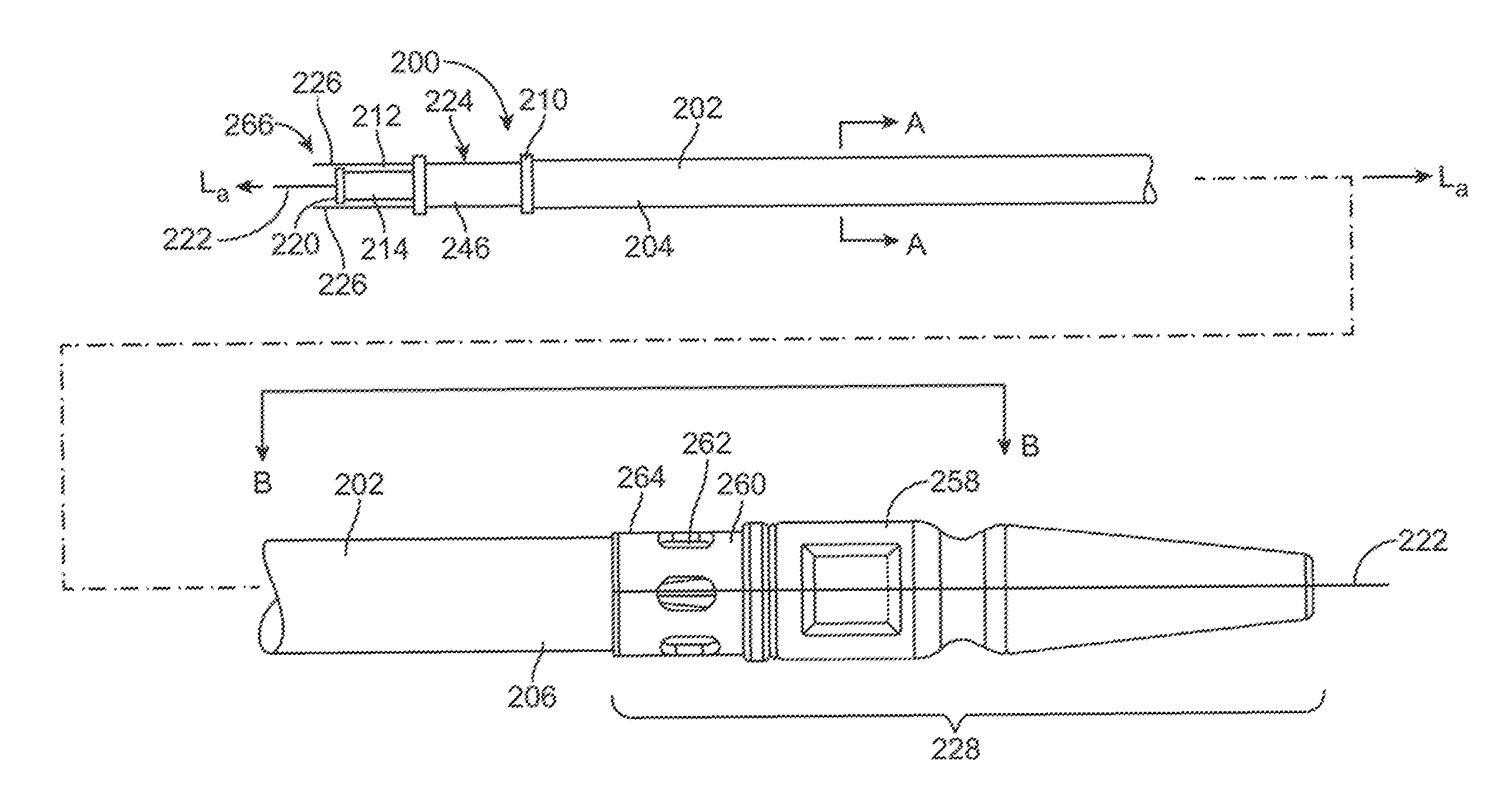
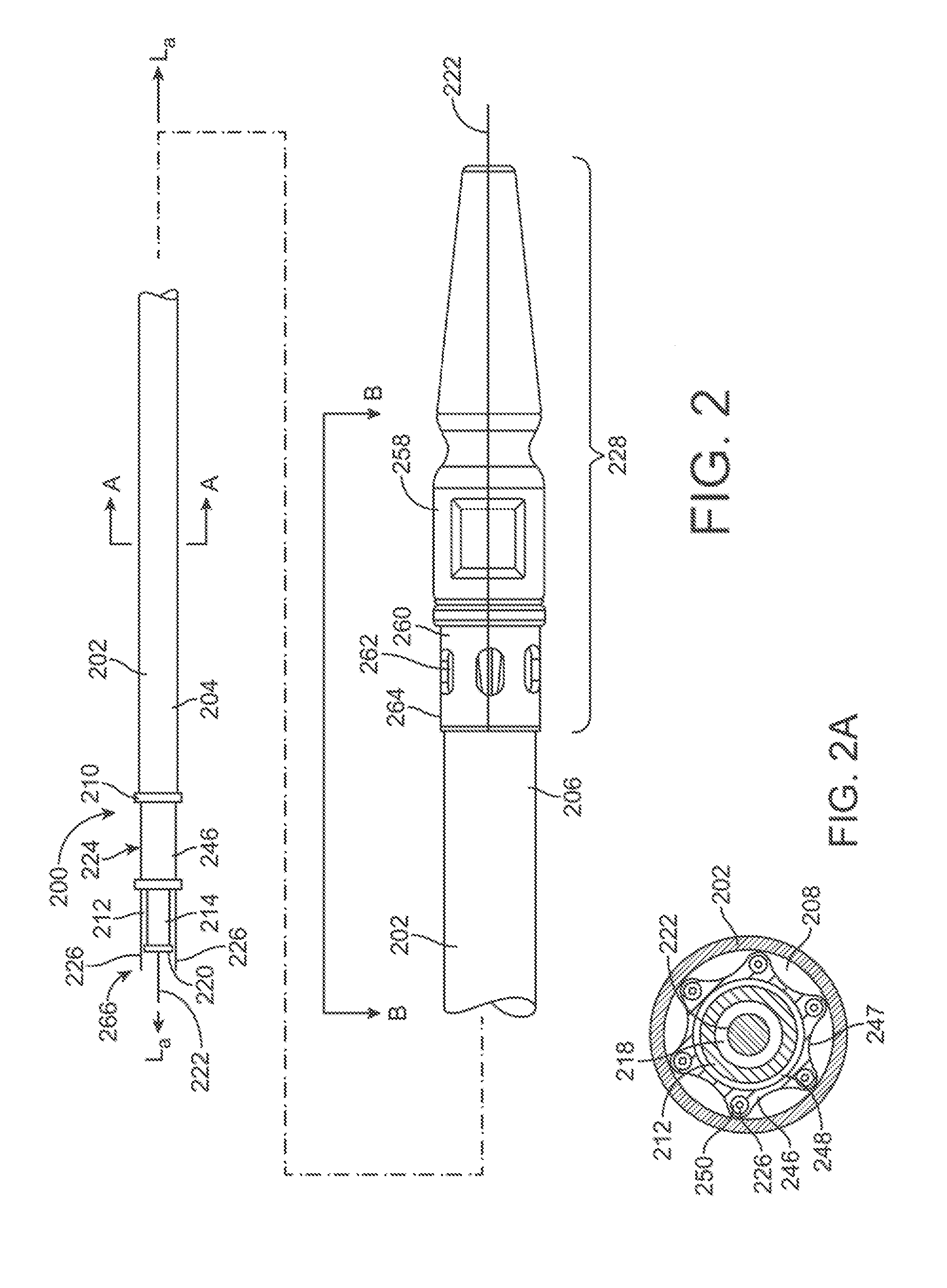
[0030]Specific embodiments of the present invention are now described with reference to the figures, wherein like reference numbers indicate identical or functionally similar elements. Specific embodiments are now described with reference to the figures, wherein like reference numbers indicate identical or functionally similar elements. Unless otherwise indicated, for the delivery system the terms “distal” and “proximal” are used in the following description with respect to a position or direction relative to the treating clinician. “Distal” and “distally” are positions distant from or in a direction away from the clinician, and “proximal” and “proximally” are positions near or in a direction toward the clinician. For the stent-graft prosthesis “proximal” is the portion nearer the heart by way of blood flow path while “distal” is the portion of the stent-graft further from the heart by way of blood flow path. In addition, the term “self-expanding” is used in the following descriptio...


PUM


Abstract

Stent-graft delivery systems having a tip capture mechanism with a plurality of elongated cables that allow for gradual deployment and repositioning of a stent-graft prosthesis. The tip capture mechanism includes a guiding assembly, a distal tip assembly, and a plurality of cables. In a first relative position, the distal tip assembly extends the guiding assembly to temporarily constrain the distal ends of the cables and an intermediate portion of each cable constrains an endmost crown of the prosthesis. In this first relative position, tension on the cables may be selectively adjusted to allow for both gradual continuous radial expansion and contraction of the endmost crowns of the stent-graft prosthesis. In a second relative position, the distal tip assembly does not extend over the guiding assembly and thus does not constrain the distal ends of the cables, and thereby the cables do not constrain the endmost crowns.

Description

FIELD OF THE INVENTION[0001]The invention is related in general to implantable prostheses and in particular to self-expanding stent-grafts.BACKGROUND OF THE INVENTION[0002]Prostheses for implantation in blood vessels or other similar organs of the living body are, in general, well known in the medical art. For example, prosthetic vascular grafts constructed of biocompatible materials have been employed to replace or bypass damaged or occluded natural blood vessels. In general, endovascular grafts typically include a graft anchoring component that operates to hold a tubular graft component of a suitable graft material in its intended position within the blood vessel. Most commonly, the graft anchoring component is one or more radially compressible stents that are radially expanded in situ to anchor the tubular graft component to the wall of a blood vessel or anatomical conduit. Thus, endovascular grafts are typically held in place by mechanical engagement and friction due to the oppo...

Claims


Application Information

Patent Timeline
Patent Type & Authority Applications(United States)
IPC IPC(8): A61F2/962
CPCA61F2/962A61F2/89A61F2/966A61F2002/9511A61F2002/9534A61F2002/9665
Inventor ARGENTINE, JEFFERYSCHMITT, JOSHUASTIGER, MARKWOLL, BRANDON
Owner MEDTRONIC VASCULAR INC
Why Eureka
Try Eureka