Self-Driven Ice Resurfacing Machine and Method for Use

Inactive Publication Date: 2014-08-28
VAN EIJL PAUL J +2
View PDF14 Cites 13 Cited by
  • Summary
  • Abstract
  • Description
  • Claims
  • Application Information

AI Technical Summary

Benefits of technology

[0009]A self-driven ice-resurfacing device for resurfacing an ice rink is disclosed. The device is comprised of several individual components contained within an exterior housing. The housing extends a width, a length, and a height of the device to enclose the components. These components operate in combination to prov

Problems solved by technology

A standard ice resurfacing vehicle is quite large, often the size of a large automobile, making it cumbersome to maneuver and operate.
In addition to being difficult

Method used


Image

  • Self-Driven Ice Resurfacing Machine and Method for Use
  • Self-Driven Ice Resurfacing Machine and Method for Use
  • Self-Driven Ice Resurfacing Machine and Method for Use

Examples


Example

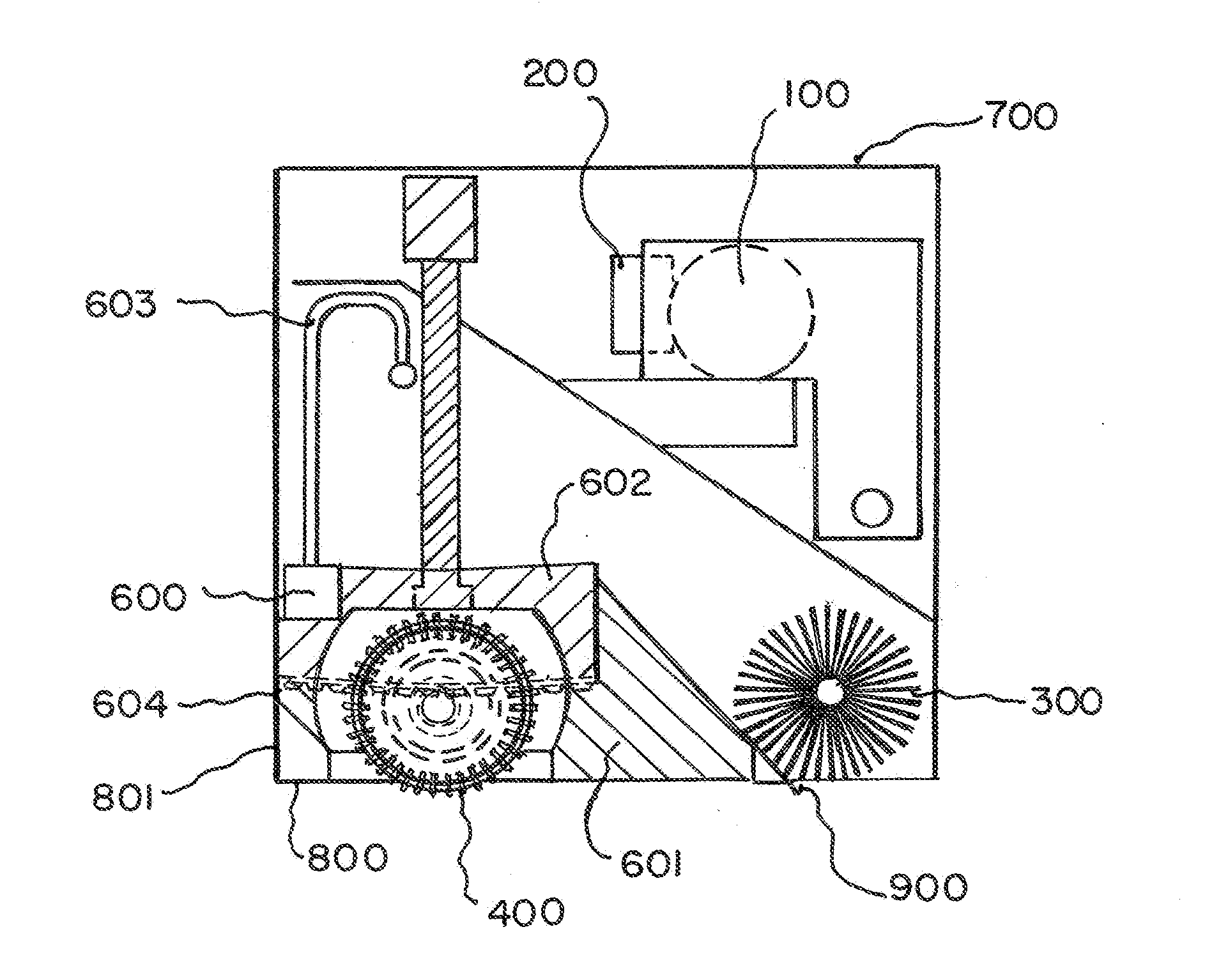
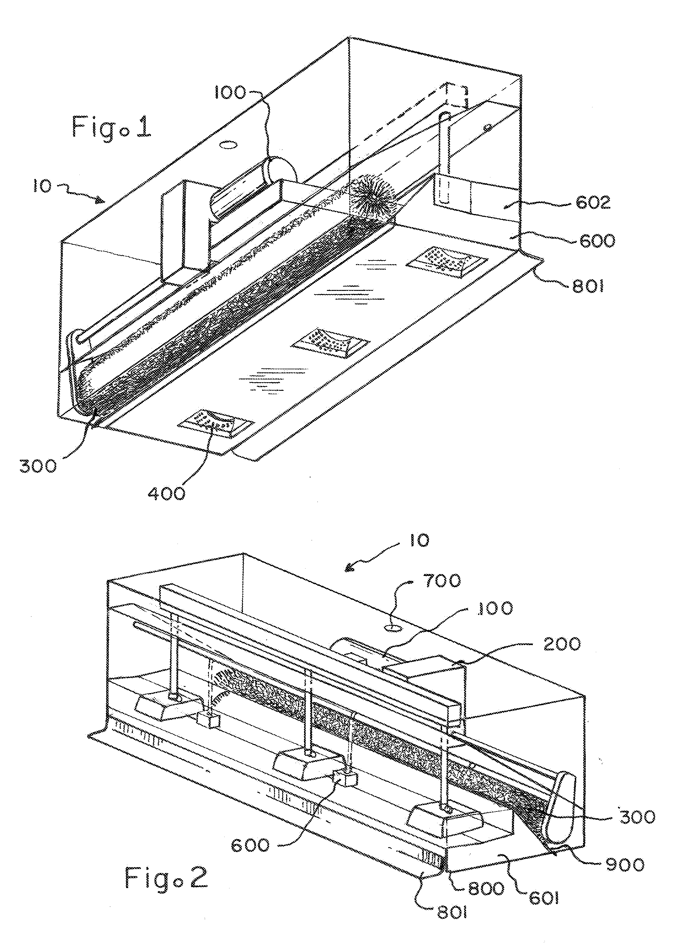
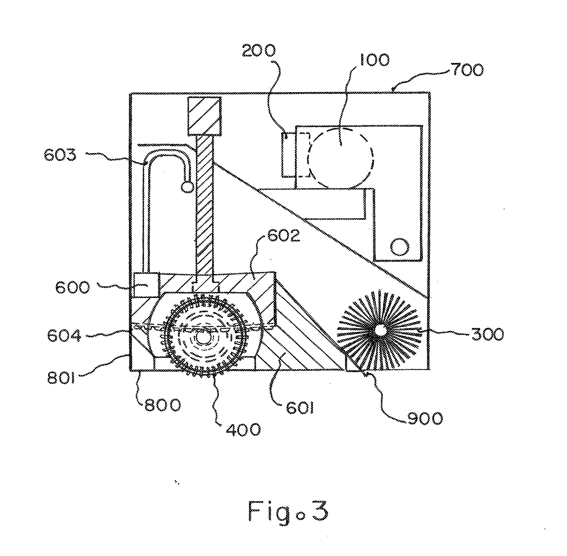
[0029]Referring now to FIG. 1-3, various views of a self-driven ice-resurfacing device, generally referred to as 10, are shown. In the preferred embodiment of the present invention, the device 10 is comprised of several individual components contained within an exterior housing. The housing extends a width, a length, and a height of the device to enclose the components. These components operate in combination to provide an efficient and effective ice resurfacing by brushing the ice, scraping the ice, heating collected ice shavings to reduce bulk and recycle the ice shavings, filtering the heated ice shavings, and depositing this filtered, heated, and recycled water back onto the ice surface at a smooth and consistent rate of flow. To accomplish this process, these several systems are powered by a motor 100 and a fuel source 200. The fuel source is preferably electric in the form of a battery or batteries, although the fuel source could be any standard low emissions fuel such as prop...


PUM


Abstract

A self-driven device to resurface an ice rink. The device includes a rotating brush to sweep the ice anterior to a blade used to the scrape the ice. Collected snow is moved into a hot water tank where it is melted and moved to a warm water tank for redeposit onto the skating surface.

Description

CROSS REFERENCE TO RELATED APPLICATIONS[0001]This application claims the benefit of provisional patent application Ser. No. 61 / 769,987 filed 2013 Feb. 27 by Paul J. van Eijl, one of the present inventors, and is herein incorporated by reference in its entirety.FEDERALLY SPONSORED RESEARCH OR DEVELOPMENT[0002]Not ApplicableSEQUENCE LISTING, A TABLE, OR A COMPUTER PROGRAM[0003]Not ApplicableFIELD OF THE INVENTION[0004]The present invention relates to a self-driven device to resurface an ice rink.BACKGROUND OF THE INVENTION[0005]A traditional ice-resurfacing machine is constructed on a vehicle chassis and operated by a user. The ice-resurfacing vehicle typically has a large storage area for collected ice shavings and includes an ice-resurfacing unit dragged behind the vehicle and around the ice needing to be resurfaced. This resurfacing unit includes a blade, augers, and watering unit. In use, the ice-resurfacing vehicle is driven onto the rink, the ice-resurfacing unit is lowered and ...

Claims


Application Information

Patent Timeline
IPC IPC(8): E01H4/02
CPCE01H4/023
Inventor VAN EIJL, PAUL J.CHRIST, KEVIN G.
Owner VAN EIJL PAUL J
Why Eureka
Try Eureka