
Modular laboratory workbench

a laboratory workbench and modular technology, applied in the field of modular laboratory workbench, can solve the problems of inefficient use of space, less than ideal mix of work spaces, and changes in technician needs, and spaces are more or less useful

Inactive Publication Date: 2014-08-28
NOVARTIS INST FOR BIOMEDICAL RES
View PDF26 Cites 41 Cited by
  • Summary
  • Abstract
  • Description
  • Claims
  • Application Information

AI Technical Summary

Benefits of technology

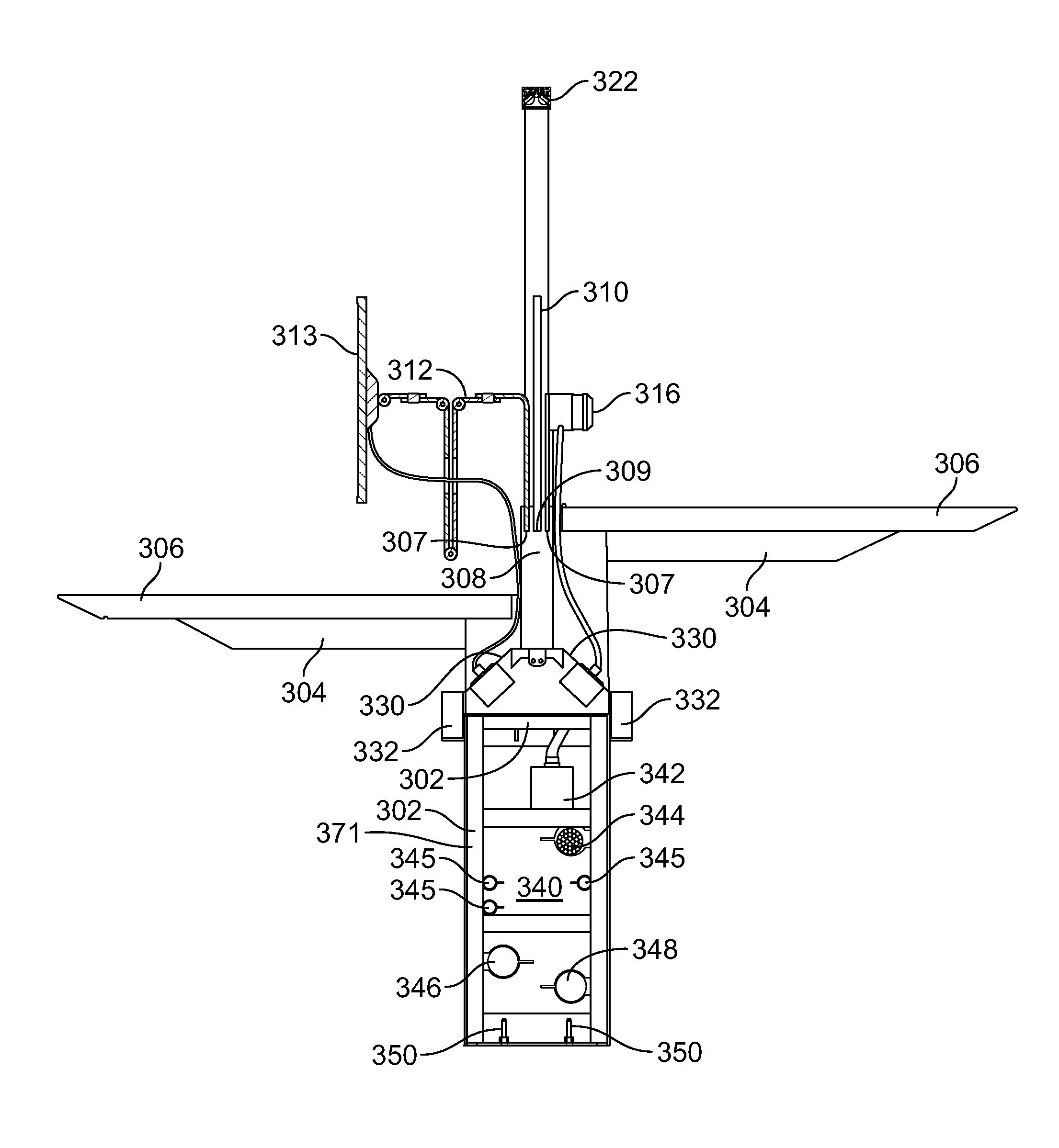
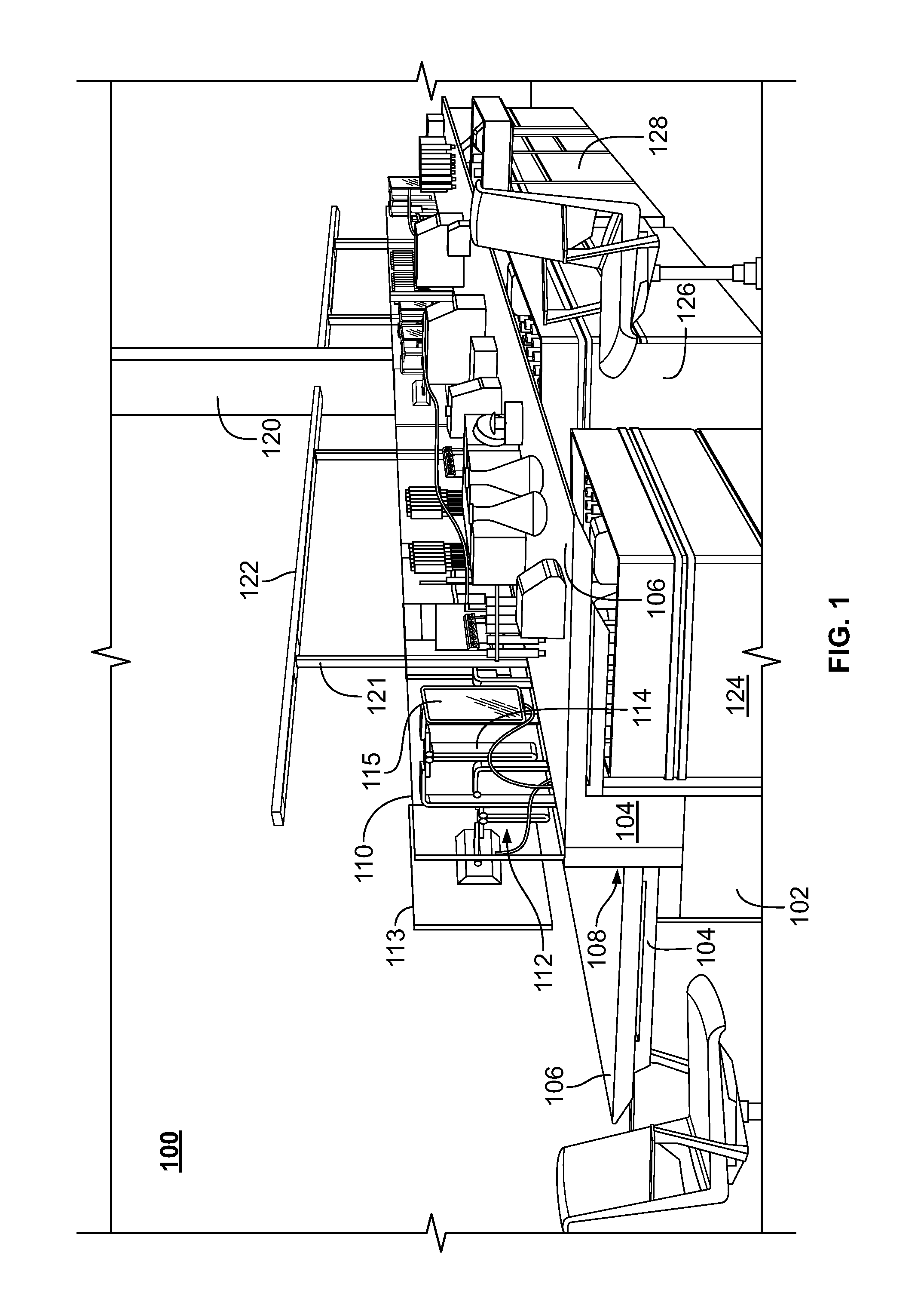
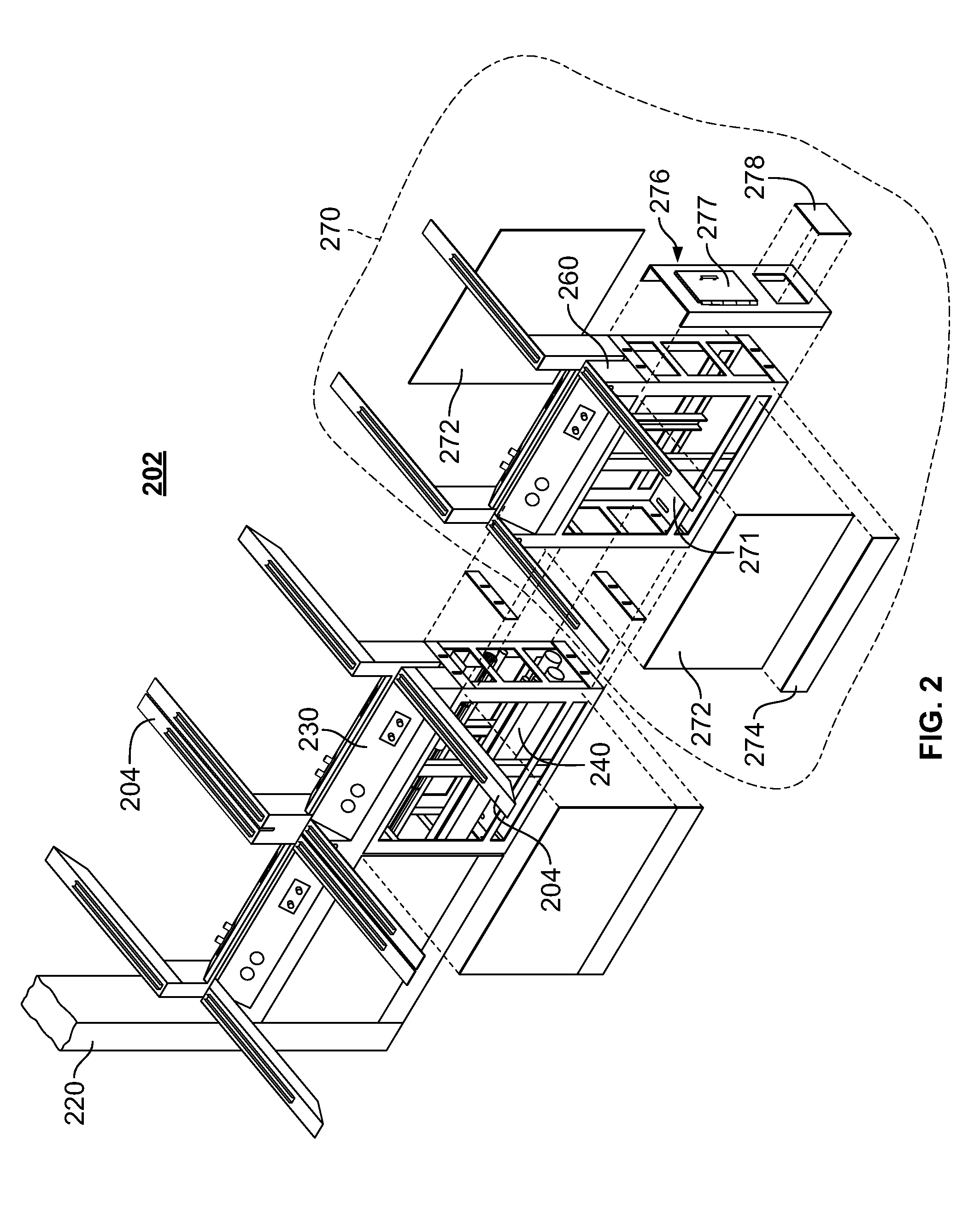
The patent text describes two different designs of modular laboratory workbenches. The first design has a spine structure that supports two or more translatable work surfaces, with an accessory support structure attached to the spine structure that runs longitudinally along the spine structure. This allows for the placement of accessories like a backsplash and work surface accessories above the spine structure. The second design has a spine structure that supports two or more cantilever brackets with two or more work surfaces attached to them. This design allows for the placement of the work surfaces above the spine structure and accessories like a backsplash and work surface accessories to be placed above the spine structure as well. These designs offer flexibility and customization options for laboratory workbenches.

Problems solved by technology

Laboratory designs pose a challenge of efficiently using available space while trying to anticipate the needs of laboratory technicians and other employees.
However, attempting to predict the needs of laboratory technicians when laying out a laboratory space may lead to inefficient use of the space and a less than ideal mix of work spaces.
Technician needs may also change over time, and the demands of different projects may make different work spaces more or less useful.
For example, some technicians may prefer to use tablet computers rather than desktop or laptop computers, and existing work spaces may be ill equipped to accommodate varying computer resources.

Method used


Image

  • Modular laboratory workbench
  • Modular laboratory workbench
  • Modular laboratory workbench

Examples


Embodiment Construction

[0020]The following description is presented to enable a person of ordinary skill in the art to make and use the various embodiments. Descriptions of specific devices, techniques, and applications are provided only as examples. Various modifications to the examples described herein will be readily apparent to those of ordinary skill in the art, and the general principles defined herein may be applied to other examples and applications without departing from the spirit and scope of the various embodiments. Thus, the various embodiments are not intended to be limited to the examples described herein and shown, but are to be accorded the scope consistent with the claims.

[0021]Various embodiments are described below relating to a modular laboratory workbench that is easily configurable to satisfy varied laboratory needs. A modular laboratory workbench may include a spine structure that is semi-permanently attached to a laboratory floor (e.g., by screws, bolts, etc.). The spine structure...


PUM


Abstract

Modular laboratory workbenches and work surface accessories are provided. Modular laboratory workbenches may include a spine structure including multiple modules with core passageways for routing utilities. At least one spine structure module may include circuit breakers behind a panel for local electrical power control. The spine structure may include a top with angled faces that provide power outlets, gas terminals, and other utilities. Between angled faces, an accessory support structure may be provided that supports a backsplash in a center channel and provides accessory slots on both sides of the center channel to receive and support interchangeable accessories including monitor arms, tablet arms, gas turrets, supplemental lights, etc. Cantilever brackets of various heights may attach to the spine structure and support work surfaces that are translatable to provide access to the utilities provided on the angled faces of the spine structure.

Description

CROSS-REFERENCE TO RELATED APPLICATIONS[0001]This application claims priority to U.S. Provisional Patent Application Ser. No. 61 / 768,335, filed Feb. 22, 2013, the entire disclosure of which is hereby incorporated by reference in its entirety for all purposes.BACKGROUND[0002]1. Field[0003]This application relates generally to workplace furniture and, more specifically, to a modular laboratory workbench for use in chemistry laboratories, biology laboratories, and the like.[0004]2. Related Art[0005]Designers, architects, developers, and the like typically strive for both functional and aesthetically pleasing use of work spaces. Laboratory designs pose a challenge of efficiently using available space while trying to anticipate the needs of laboratory technicians and other employees. To accommodate the various needs of laboratory technicians, varying work spaces may be provided in the same laboratory area. For example, work surfaces may be provided for use while a technician is standing,...

Claims


Application Information

Patent Timeline
Patent Type & Authority Applications(United States)
IPC IPC(8): A47B37/00A47B21/06
CPCA47B37/00A47B21/06A47B13/003B01L9/02A47B2021/064A47B2037/005B01L2200/028
Inventor FISHMAN, MARK C.MORI, TOSHIKOBROWN, LANDON S.
Owner NOVARTIS INST FOR BIOMEDICAL RES
Learn More