
Cutting elements including non-planar interfaces, earth-boring tools including such cutting elements, and methods of forming cutting elements

a technology of cutting elements and non-planar interfaces, applied in the direction of manufacturing tools, other chemical processes, chemistry apparatus and processes, etc., can solve the problem of high internal stresses within the diamond tabl

Active Publication Date: 2014-08-28
BAKER HUGHES INC
View PDF14 Cites 26 Cited by
  • Summary
  • Abstract
  • Description
  • Claims
  • Application Information

AI Technical Summary

Benefits of technology

The patent describes cutting elements for earth-boring tools that have a non-planar interface between a substrate and a polycrystalline table secured to the substrate. The non-planar interface includes a cross-shaped groove and L-shaped grooves. The transitions between surfaces at the interface are rounded. The cutting elements are formed by positioning particles of superhard material adjacent the non-planar end of the substrate, and sintering them in the presence of a catalyst material to form a polycrystalline table secured to the substrate. The technical effect of this design is improved wear resistance and reduced damage to the substrate, making the tools more durable and efficient during drilling operations.

Problems solved by technology

As the diamond table of the cutting element interacts with the underlying earth formation, for example by shearing or crushing, the diamond table may delaminate, spall, or otherwise fracture because of the high forces acting on the cutting element and resulting high internal stresses within the diamond table of the cutting element.

Method used


Image

  • Cutting elements including non-planar interfaces, earth-boring tools including such cutting elements, and methods of forming cutting elements
  • Cutting elements including non-planar interfaces, earth-boring tools including such cutting elements, and methods of forming cutting elements
  • Cutting elements including non-planar interfaces, earth-boring tools including such cutting elements, and methods of forming cutting elements

Examples


embodiment 1

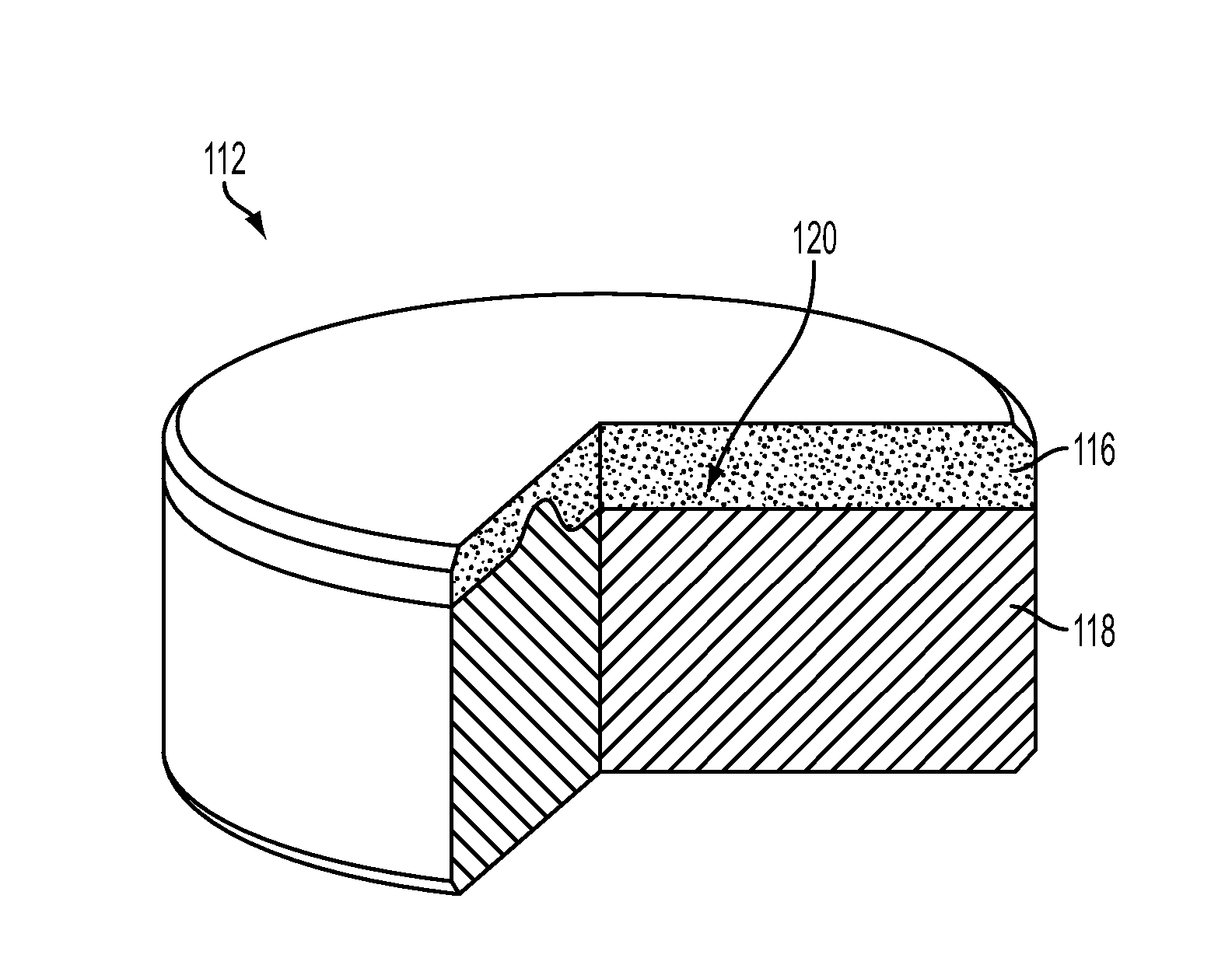
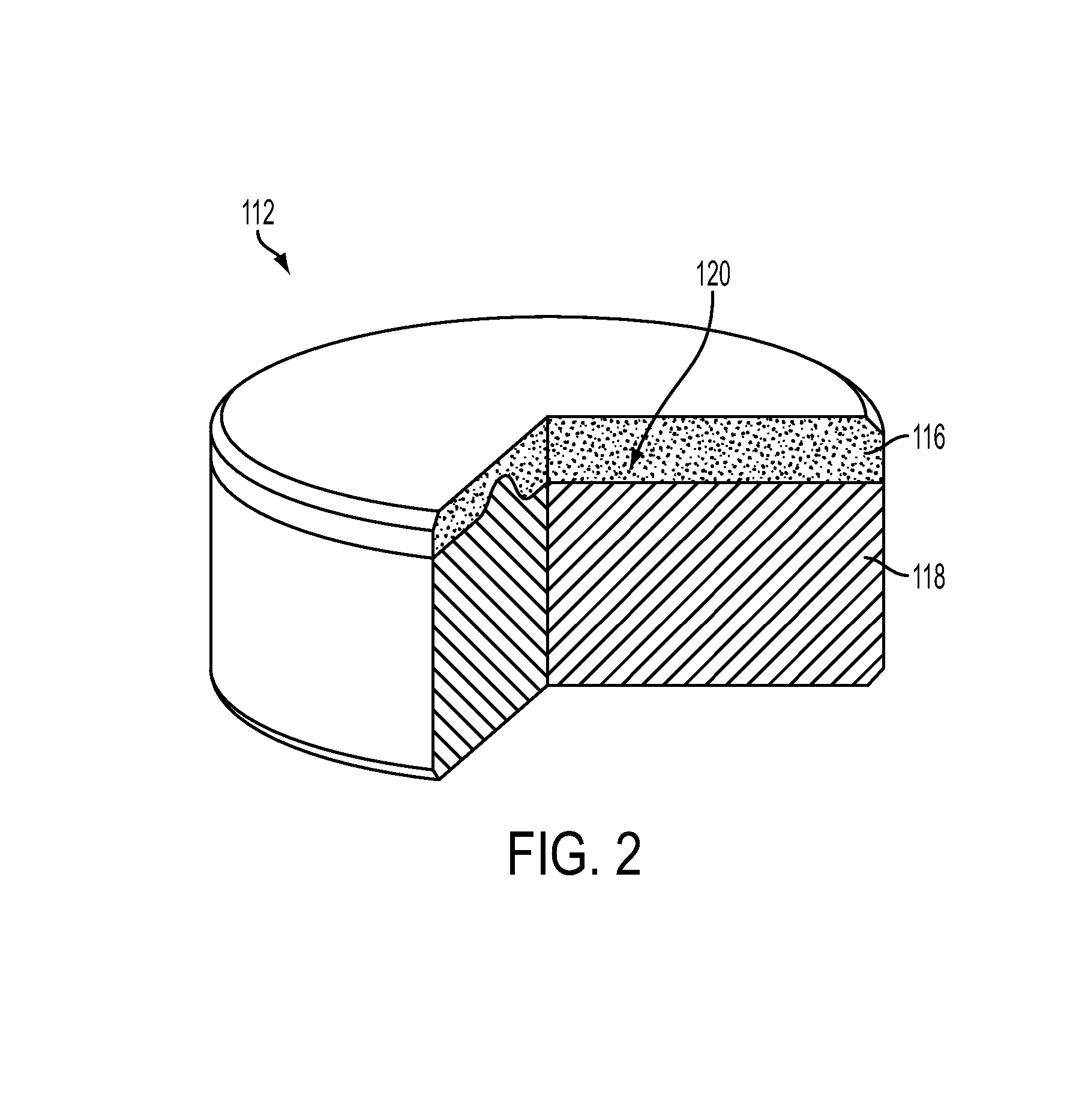
[0056]A cutting element for an earth-boring tool comprises a substrate, a polycrystalline table comprising superhard material secured to the substrate at an end of the substrate, and a non-planar interface defined between the polycrystalline table and the substrate. The non-planar interface comprises a cross-shaped groove extending into one of the substrate and the polycrystalline table and L-shaped grooves extending into the other of the substrate and the polycrystalline table proximate corners of the cross-shaped groove. Transitions between surfaces defining the non-planar interface are rounded.

embodiment 2

[0057]The cutting element of Embodiment 1, further comprising a tapered surface in an area between arms of each of the L-shaped grooves, the tapered surface extending from an intersect point of each of the L-shaped grooves toward the one of the substrate and the polycrystalline table.

embodiment 3

[0058]The cutting element of Embodiment 2, further comprising concentric grooves extending from each tapered surface into the other of the substrate and the polycrystalline table, wherein the concentric grooves do not intersect with the arms of the L-shaped grooves and a center of curvature of each of the concentric grooves is located at a central axis of the cutting element.


PUM


Abstract

Cutting elements for earth-boring tools may comprise a substrate, a polycrystalline table comprising superhard material secured to the substrate at an end of the substrate, and a non-planar interface defined between the polycrystalline table and the substrate. The non-planar interface may comprise a cross-shaped groove extending into one of the substrate and the polycrystalline table and L-shaped grooves extending into the other of the substrate and the polycrystalline table proximate corners of the cross-shaped groove. Transitions between surfaces defining the non-planar interface may be rounded. Methods of forming cutting elements for earth-boring tools may comprise forming a substrate to have a non-planar end. The non-planar end of the substrate may be provided adjacent particles of superhard material to impart an inverse shape to the particles. The particles may be sintered to form a polycrystalline table, with a non-planar interface defined between the substrate and the polycrystalline table.

Description

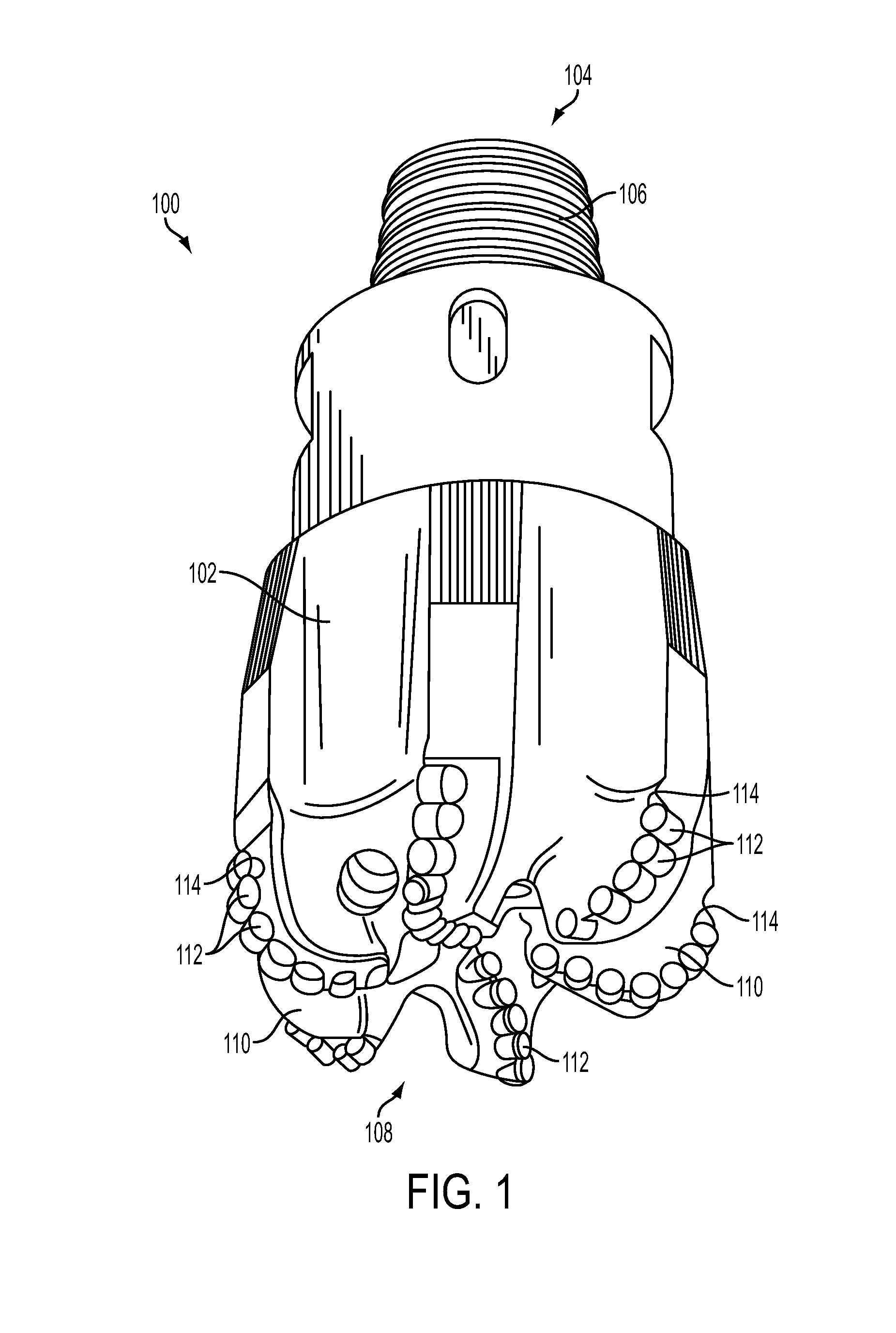
FIELD[0001]The disclosure relates generally to cutting elements for earth-boring tools. More specifically, disclosed embodiments relate to non-planar interfaces between polycrystalline tables and substrates of cutting elements for earth-boring tools that may manage stress in regions of the polycrystalline table and interrupt crack propagation through the polycrystalline table.BACKGROUND[0002]Earth-boring tools for forming wellbores in subterranean earth formations may include cutting elements secured to a body. For example, fixed-cutter earth-boring rotary drill bits (also referred to as “drag bits”) include cutting elements that are fixedly attached to a bit body of the drill bit. Roller cone earth-boring rotary drill bits may include cones that are mounted on bearing pins extending from legs of a bit body such that each cone is capable of rotating about the bearing pin on which it is mounted. Cutting elements may extend from each cone of the drill bit.[0003]The cutting elements us...

Claims


Application Information

Patent Timeline
IPC IPC(8): E21B10/573
CPCE21B10/5735
Inventor NELMS, DEREK L.DOSTER, MICHAEL L.DEGEORGE, JARODFUSELIER, DANIELLE M.
Owner BAKER HUGHES INC
Learn More