
In-mold decoration molding method and in-mold decoration molding machine

a technology of decoration molding and decoration molding machine, which is applied in the field of in-mold decoration molding, can solve the problems of reducing the positioning accuracy of the pattern on the surface of the molded body, affecting and affecting the application of the decorated sheet, so as to achieve high positioning accuracy, prevent the displacement of the predetermined portion, and improve the appearance of the molded obj

Active Publication Date: 2014-08-28
PANASONIC INTELLECTUAL PROPERTY MANAGEMENT CO LTD
View PDF2 Cites 5 Cited by
  • Summary
  • Abstract
  • Description
  • Claims
  • Application Information

AI Technical Summary

Benefits of technology

The present invention provides an in-mold decoration molding method and machine that improves the appearance of molded articles by preventing deformation of the decorated sheet during the molding process. This is achieved by adjusting the inclination of the surfaces of the decorated sheet and specifying the first contact position of the clamping member with the decorated sheet. This ensures that the pattern transferred to the surface of the molded article is not displaced and increases reproducibility, even if the decorated sheet is separated from the parting face and tension is applied.

Problems solved by technology

However, even if the decorated sheet is located in parallel or substantially in parallel with the parting face of the die, the first contact position of the clamping member with the decorated sheet varies as long as the members of the molding machine actually have a dimension error and an alignment error.
Thus, the pattern of the decorated sheet is displaced also because the first contact position of the clamping member with the decorated sheet is varied by a dimension error and an alignment error of the members of the molding machine.
This may reduce the positioning accuracy of the pattern on the surface of the molded body.
If the pattern transferred to the surface of the molded article contains a logo requiring high positioning accuracy, a displacement of the logo pattern is a major factor leading to a faulty appearance of the molded article.

Method used


Image

  • In-mold decoration molding method and in-mold decoration molding machine
  • In-mold decoration molding method and in-mold decoration molding machine
  • In-mold decoration molding method and in-mold decoration molding machine

Examples


first embodiment

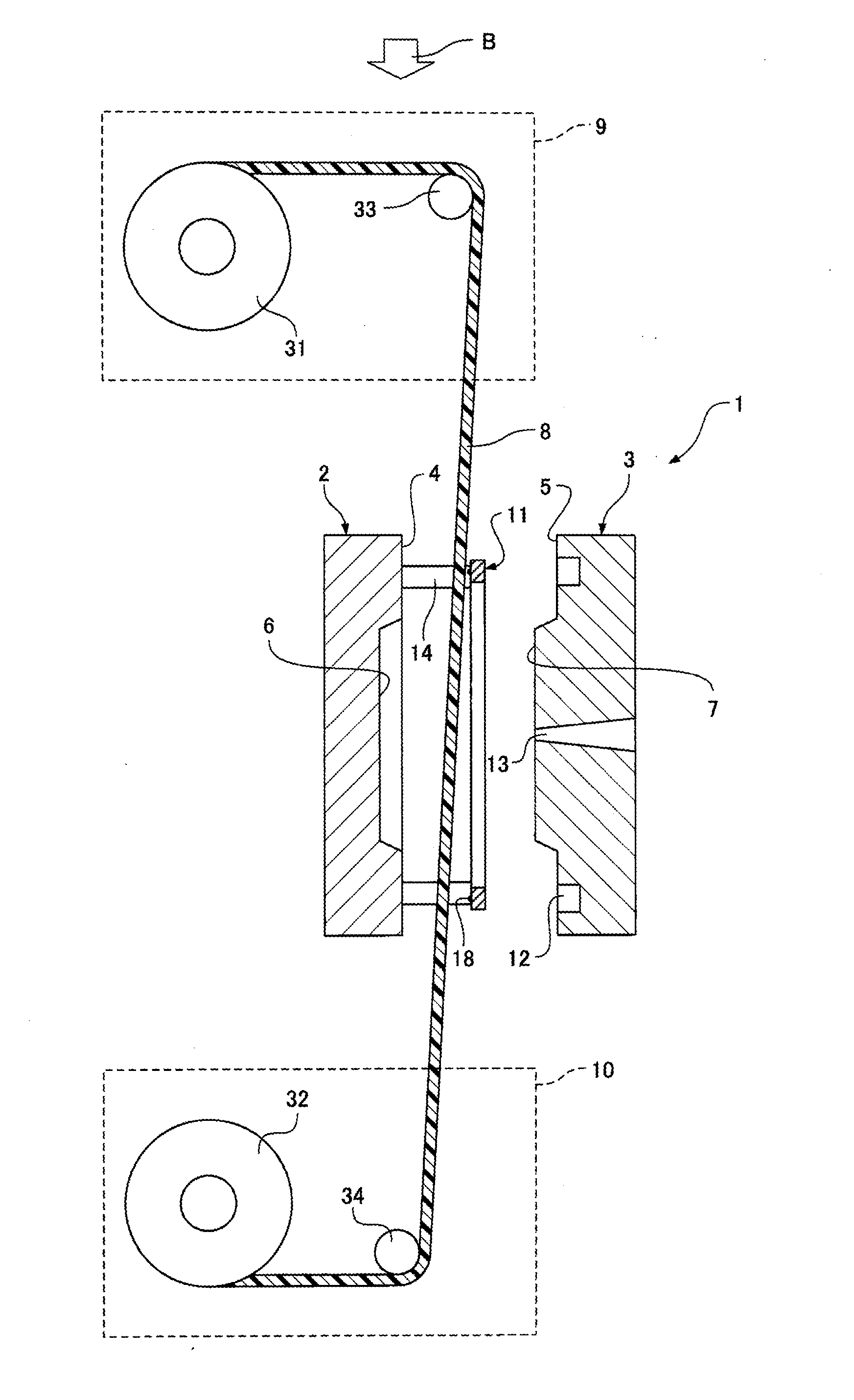
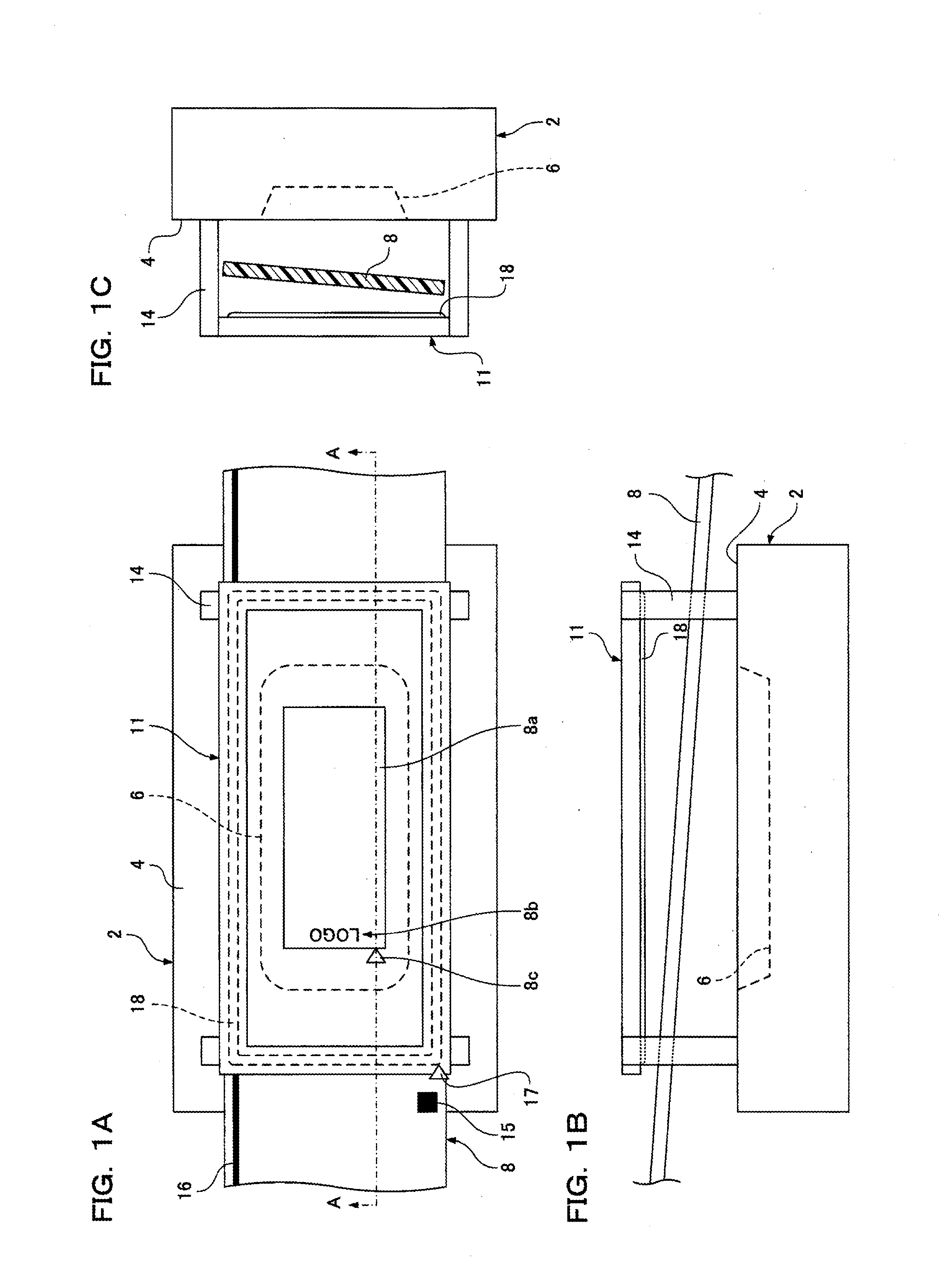
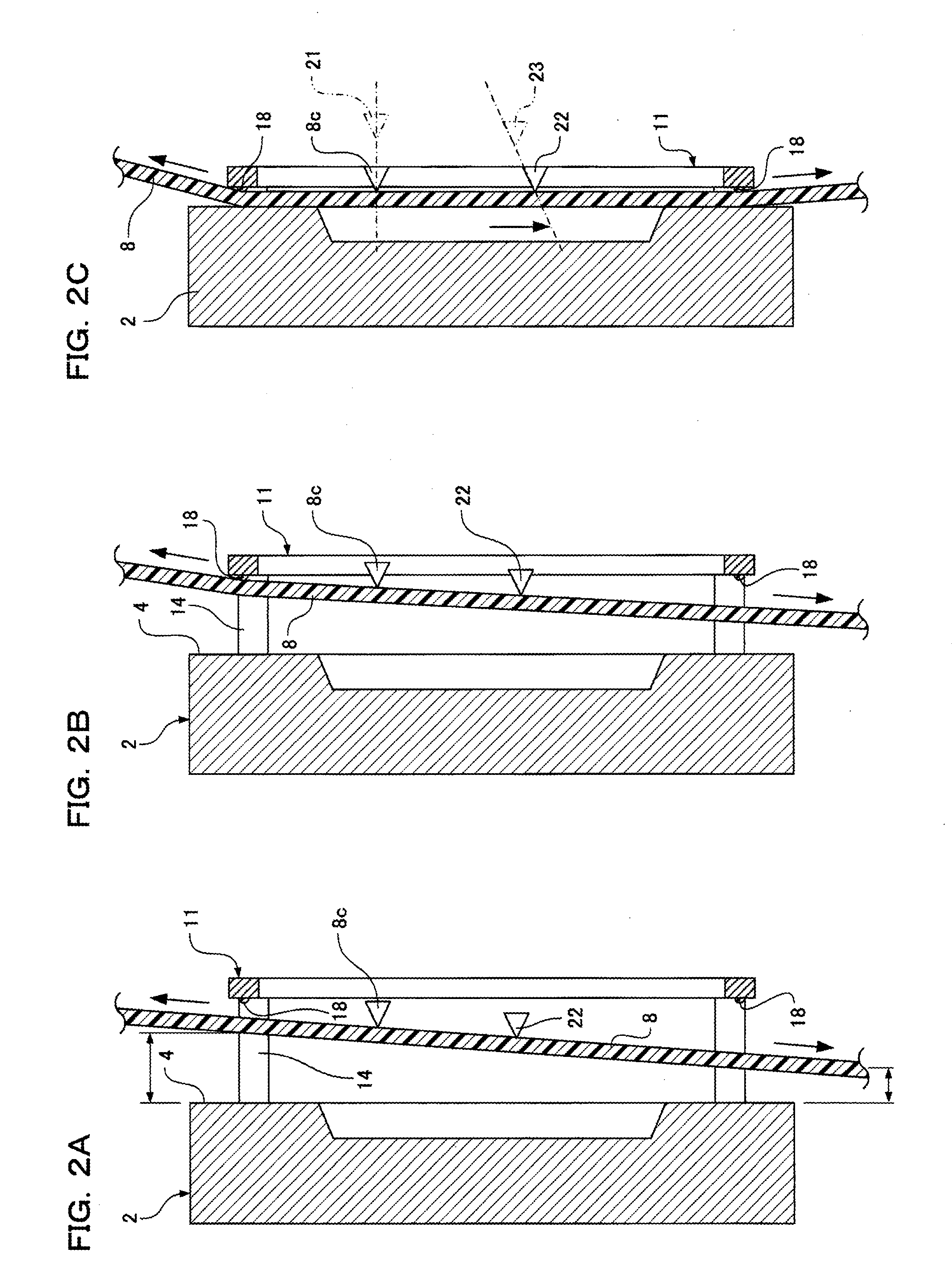
[0048]FIG. 1A is a plan view schematically illustrating the structure of an A die of a pair of molding / decorating dies and a decorated sheet in an in-mold decoration molding machine according to a first embodiment of the present invention. FIG. 1B is a side view illustrating the layout of the decorated sheet relative to the A die. FIG. 1C is a front view illustrating the layout of the decorated sheet relative to the A die. FIGS. 2A to 2C are cross-sectional views for explaining the operations of the in-mold decoration molding machine according to the first embodiment of the present invention. FIGS. 2A to 2C schematically illustrate the cross sections of the A die and the decorated sheet that are cut along the line A-A of FIG. 1A. FIG. 3 is a cross-sectional view schematically illustrating the structure of the in-mold decoration molding machine according to the first embodiment of the present invention.

[0049]As shown in FIG. 3, the in-mold decoration molding machine according to the ...

second embodiment

[0096]In a second embodiment, only different points from the first embodiment will be described below. FIG. 5A is a plan view schematically illustrating the structure of an A die of a pair of molding / decorating dies and a decorated sheet in an in-mold decoration molding machine according to the second embodiment of the present invention. FIG. 5B is a cross-sectional view illustrating the layout of the decorated sheet with respect to the A die. Members corresponding to the respective members of the first embodiment are indicated by the same reference numerals as in the first embodiment.

[0097]The second embodiment is different from the first embodiment in that the parting faces of a pair of molding / decorating dies 1 each include an inclined surface having a cavity face. FIG. 5B illustrates an inclined surface (a part of the parting face) 52 diagonal to a platen surface 51 of an A die 2.

[0098]In the case where the cavity face is formed on the inclined surface (a part of the parting fac...


PUM

PropertyMeasurementUnit
tensionaaaaaaaaaa
tensionaaaaaaaaaa
distancesaaaaaaaaaa

Abstract

The surfaces of a decorated sheet are tilted with respect to a parting face before a movement of a clamping member. When the clamping member moves to press the decorated sheet under tension to the parting face, a part of the clamping member first comes into contact with the decorated sheet at a position determined by inclination of the surfaces of the decorated sheet and then another portion of the clamping member comes into contact with the decorated sheet.

Description

TECHNICAL FIELD[0001]The present invention relates to in-mold decoration molding for obtaining molded articles with decoration.BACKGROUND ART[0002]In-mold decoration molding is used for producing injection-molded articles with patterns. An in-mold decoration molding method includes the steps of: disposing a pattern of a decorated sheet in a molding space (cavity) formed in molds serving as forming dies; injecting molten resin into the molding space; and removing a molded article (product) from the molding space. According to the in-mold decoration molding method, the pattern held on the decorated sheet is transferred to the surface of the molded article in a resin injection molding process. Thus, the molded article is obtained with decoration. A typical in-mold decoration molding process includes the following steps:[0003]First, a roll of a decorated sheet is prepared. The decorated sheet includes a base sheet and a transfer layer disposed on the base sheet. The transfer layer inclu...

Claims


Application Information

Patent Timeline
Patent Type & Authority Applications(United States)
IPC IPC(8): B29C45/00
CPCB29C45/0055B29C45/14262B29C45/14016B29C45/14065
Inventor NAKAGAWA, TAKASHIHIRAISHI, MASAKAZUYABE, AKIRA
Owner PANASONIC INTELLECTUAL PROPERTY MANAGEMENT CO LTD
Learn More