Short light pulse generation device, terahertz wave generation device, camera, imaging device, and measurement device

a generation device and terahertz wave technology, applied in the field of short light pulse generation devices, can solve the problems of distorted pulse waveforms, inability to control, and inability to obtain desired pulse width, and achieve the effect of reducing the size of the devi

Inactive Publication Date: 2014-08-28
SEIKO EPSON CORP
View PDF1 Cites 13 Cited by
  • Summary
  • Abstract
  • Description
  • Claims
  • Application Information

AI Technical Summary

Benefits of technology

[0011]In such a short light pulse generation device, since the light path lengths of a plurality of light pulses before the light pulse is branched in the light branching portion and then incident on the group velocity dispersion portion are equal to each other, the plurality of light pulses which are branched and incident on the group velocity dispersion portion can be set to in-phase. Thereby, the group velocity dispersion portion can have positive group velocity dispersion characteristics. In this manner, according to the short light pulse generation device, since the group velocity dispersion portion can be controlled so as to have positive group velocity dispersion characteristics, it is possible to obtain a light pulse having a desired pulse width.
[0015]In a short light pulse generation device, since the light branching portion produces a light path difference in the plurality of branched light pulses which are set to have opposite phases to each other and are incident on the group velocity dispersion portion, the plurality of light pulses which are branched and incident on the group velocity dispersion portion can be set to have opposite phases. Thereby, the group velocity dispersion portion can have negative group velocity dispersion characteristics. In this manner, according to the short light pulse generation device, since the group velocity dispersion portion can be controlled so as to have negative group velocity dispersion characteristics, it is possible to obtain a light pulse having a desired pulse width.
[0021]In such a terahertz wave generation device, the short light pulse generation device according to the above aspect is included, and thus it is possible to achieve a reduction in the size thereof.
[0023]In such a camera, the short light pulse generation device according to the above aspect is included, and thus it is possible to achieve a reduction in the size thereof.
[0025]In such an imaging device, the short light pulse generation device according to the above aspect is included, and thus it is possible to achieve a reduction in the size thereof.
[0027]In such a measurement device, the short light pulse generation device according to the above aspect is included, and thus it is possible to achieve a reduction in the size thereof.

Problems solved by technology

However, the group velocity dispersion compensator disclosed in JP-A-10-213714 is not able to control whether the group velocity dispersion compensator has positive group velocity dispersion characteristics or negative group velocity dispersion characteristics.
For this reason, in the short light pulse generation device including the group velocity dispersion compensator disclosed in JP-A-10-213714, there is a problem in that a desired pulse width is not obtained.
In addition, when the group velocity dispersion compensator has both positive group velocity dispersion characteristics and negative group velocity dispersion characteristics, pulse waveforms are distorted, and as a result, a desired pulse width may not be obtained.
As mentioned above, in the short light pulse generation device, when the group velocity dispersion characteristics of the group velocity dispersion compensator are not able to be controlled, a desired pulse width may not be obtained.

Method used


Image

  • Short light pulse generation device, terahertz wave generation device, camera, imaging device, and measurement device
  • Short light pulse generation device, terahertz wave generation device, camera, imaging device, and measurement device
  • Short light pulse generation device, terahertz wave generation device, camera, imaging device, and measurement device

Examples


first embodiment

1. First Embodiment

1.1. Configuration of Short Light Pulse Generation Device

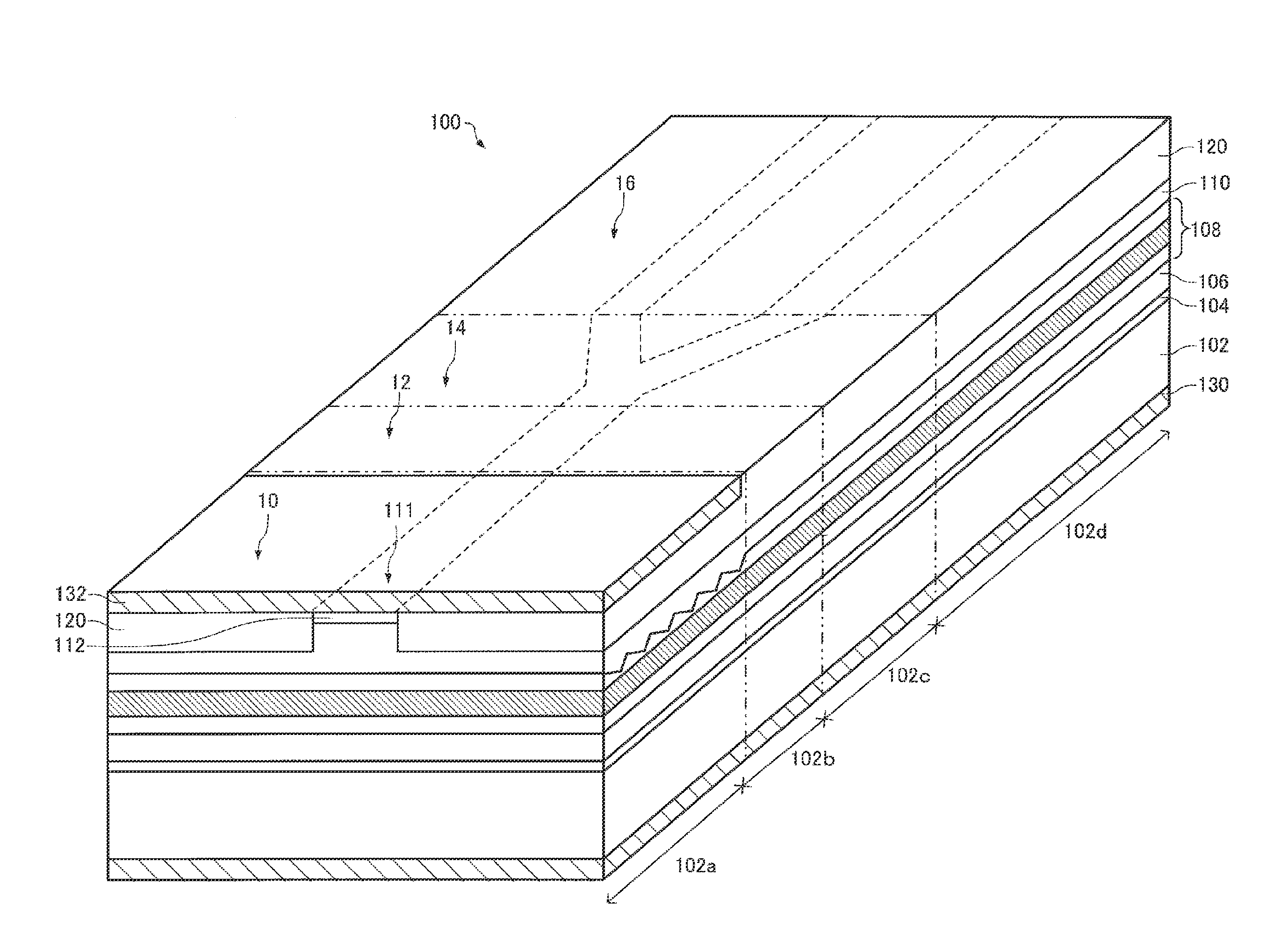
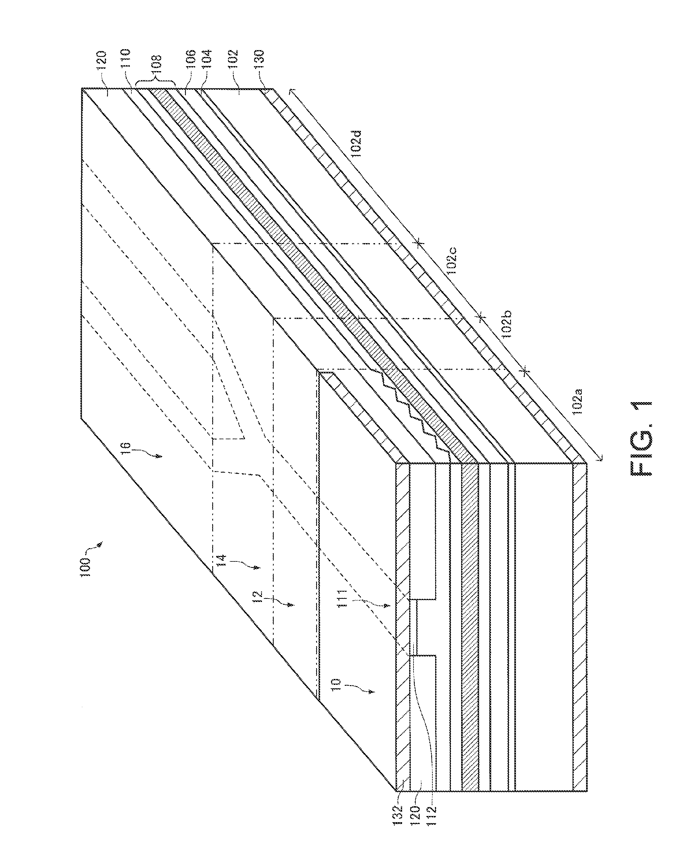
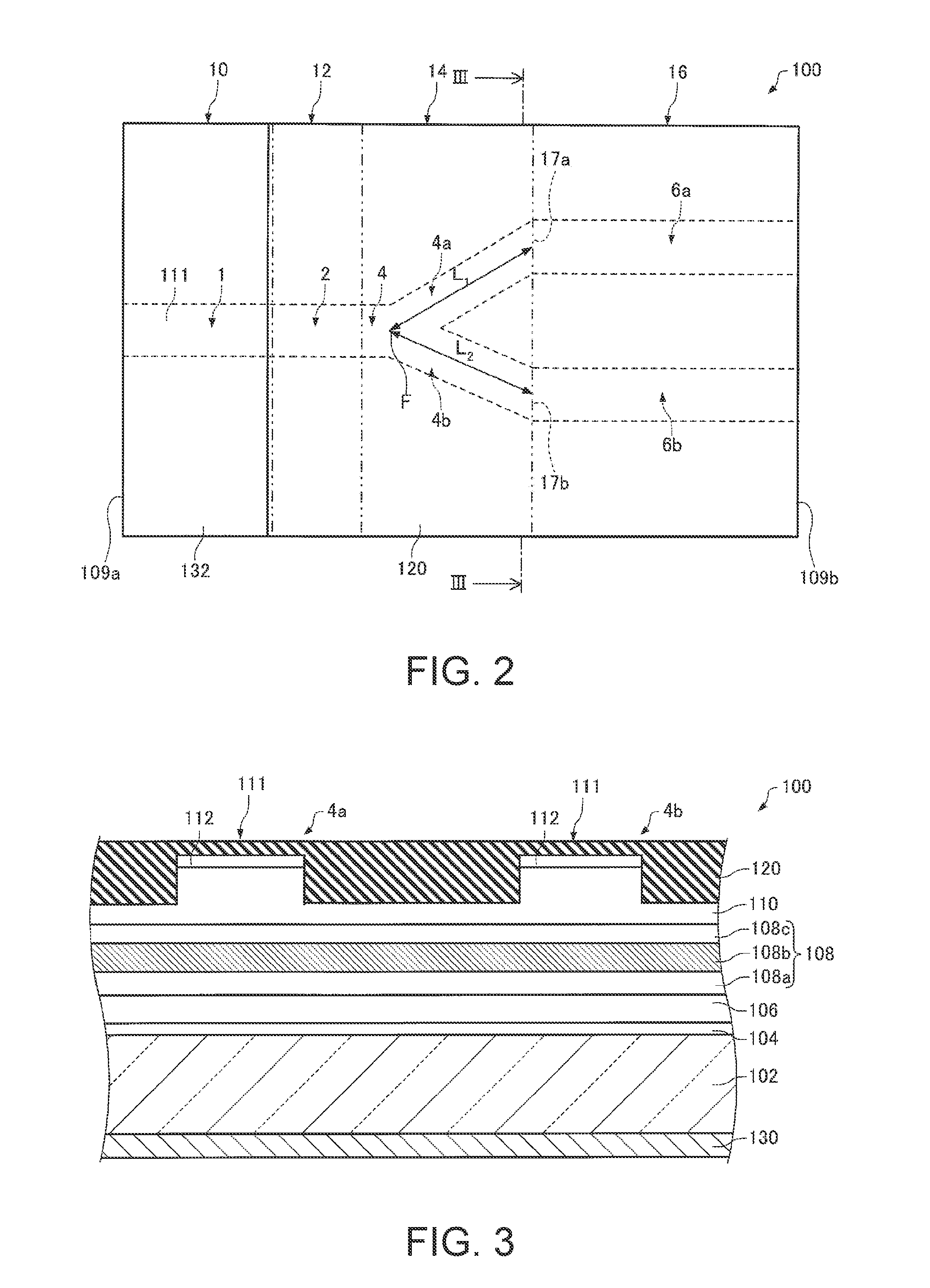
[0065]First, a short light pulse generation device 100 according to a first embodiment will be described with reference to the accompanying drawings. FIG. 1 is a perspective view schematically illustrating the short light pulse generation device 100 according to the embodiment. FIG. 2 is a plan view schematically illustrating the short light pulse generation device 100 according to the embodiment.

[0066]As shown in FIGS. 1 and 2, the short light pulse generation device 100 includes a light pulse generation portion 10 that generates a light pulse, a frequency chirping portion 12 that chirps a frequency of a light pulse, a light branching portion 14 that branches the chirped light pulse, and a group velocity dispersion portion 16 that produces a group velocity difference depending on wavelengths with respect to a plurality of branched light pulses.

[0067]The light pulse generation portion 10 generates a light pu...

third modification example

3. Third Modification Example

[0155]Next, a third modification example will be described. FIG. 14 is a plan view schematically illustrating a short light pulse generation device 400 according to the third modification example. FIG. 15 is a cross-sectional view schematically illustrating the short light pulse generation device 400 according to the third modification example. Meanwhile, FIG. 15 is a cross-sectional view taken along line XV-XV of FIG. 14.

[0156]In the above-mentioned short light pulse generation device 100, as shown in FIGS. 1 and 2, the light pulse generation portion 10, the frequency chirping portion 12, and the group velocity dispersion portion 16 are integrally provided.

[0157]On the other hand, in the short light pulse generation device 400, as shown in FIGS. 14 and 15, the light pulse generation portion 10, the frequency chirping portion 12, the light branching portion 14 and the group velocity dispersion portion 16 are separately provided. That is, in the short lig...

fourth modification example

4. Fourth Modification Example

[0159]Next, a fourth modification example will be described. FIG. 16 is a plan view schematically illustrating a short light pulse generation device 500 according to the fourth modification example. FIG. 17 is a cross-sectional view schematically illustrating the short light pulse generation device 500 according to the fourth modification example. Meanwhile, FIG. 17 is a cross-sectional view taken along line XVII-XVII of FIG. 16.

[0160]In the above-mentioned short light pulse generation device 100, as shown in FIG. 1, the light pulse generation portion 10 is a DFB laser.

[0161]On the other hand, in the short light pulse generation device 500, as shown in FIG. 17, the light pulse generation portion 10 is a Fabry-Perot-type semiconductor laser.

[0162]In the short light pulse generation device 500, a groove portion 510 is provided at a boundary between the first region 102a and the second region 102b when seen in plan view (when seen from the lamination direc...


PUM

PropertyMeasurementUnit
frequencyaaaaaaaaaa
refractive indexaaaaaaaaaa
wavelengthaaaaaaaaaa

Abstract

A short light pulse generation device includes: a light pulse generation portion that has a quantum well structure and generates a light pulse; a frequency chirping portion that has a quantum well structure and chirps a frequency of the light pulse; a light branching portion that branches a chirped light pulse; and a group velocity dispersion portion that has a plurality of optical waveguides, on which each of a plurality of the light pulses branched in the light branching portion is incident, and produces a group velocity difference depending on a wavelength with respect to a plurality of branched light pulses, wherein light path lengths of the light pulses in a plurality of light paths before the light pulse is branched in the light branching portion and then incident on the plurality of optical waveguides of the group velocity dispersion portion are equal to each other.

Description

BACKGROUND[0001]1. Technical Field[0002]The present invention relates to a short light pulse generation device, a terahertz wave generation device, a camera, an imaging device, and a measurement device.[0003]2. Related Art[0004]In recent years, terahertz waves which are electromagnetic waves having a frequency equal to or greater than 100 GHz and equal to or less than 30 THz have attracted attention. The terahertz waves can be used in, for example, various types of measurement such as imaging and spectroscopic measurement, non-destructive tests, and the like.[0005]Terahertz wave generation devices that generate terahertz waves include, for example, a short light pulse generation device that generates a light pulse having a pulse width of approximately subpicoseconds (several hundred femtoseconds), and a photoconductive antenna that generates a terahertz wave by irradiation with the light pulse generated in the short light pulse generation device.[0006]As a short light pulse generati...

Claims


Application Information

Patent Timeline
Patent Type & Authority Applications(United States)
IPC IPC(8): H01S5/00G01N21/35H01S5/34H01S5/12
CPCH01S5/0057G01N21/3586H01S5/34H01S5/026H01S5/0657H01S5/12H01S5/34313G01N21/3581B82Y20/00G02B6/125
Inventor NAKAYAMA, HITOSHI
Owner SEIKO EPSON CORP
Why Eureka
Try Eureka