
Fixing device and image forming apparatus with same

a technology of fixing device and image forming apparatus, which is applied in the direction of electrographic process apparatus, instruments, optics, etc., can solve the problems of easy wear of fixing belt and fixing nip-forming member, shortening waiting time, and reducing heat capacity, so as to achieve smooth slide and less fiber density

Inactive Publication Date: 2014-08-28
RICOH KK
View PDF3 Cites 17 Cited by
  • Summary
  • Abstract
  • Description
  • Claims
  • Application Information

AI Technical Summary

Benefits of technology

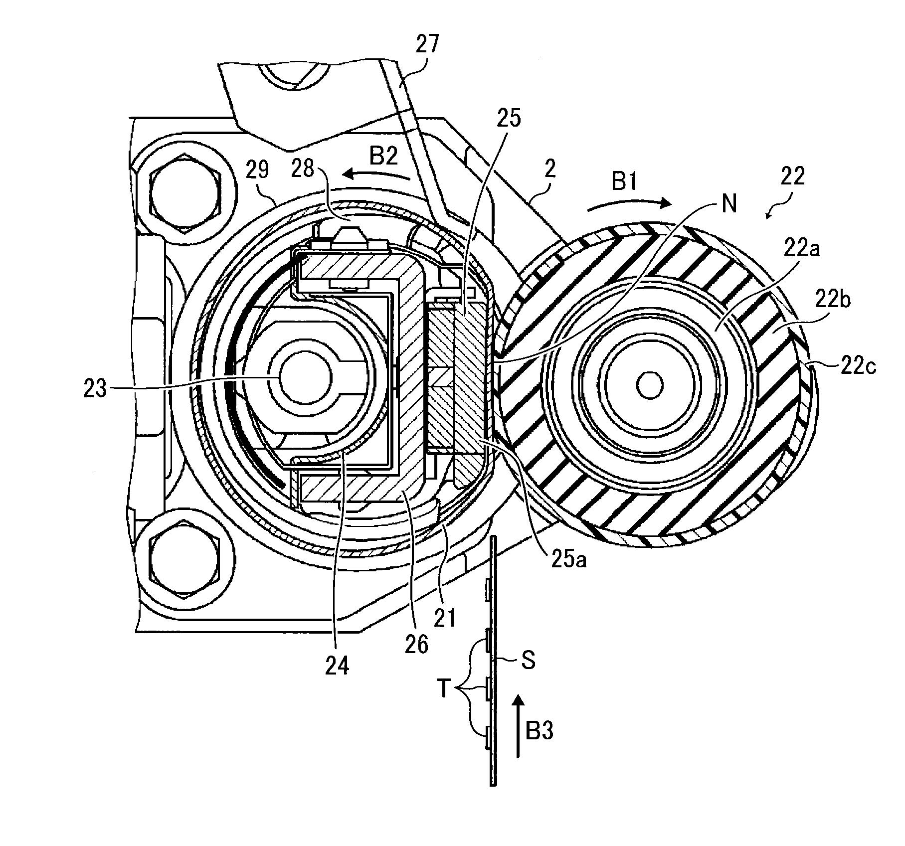
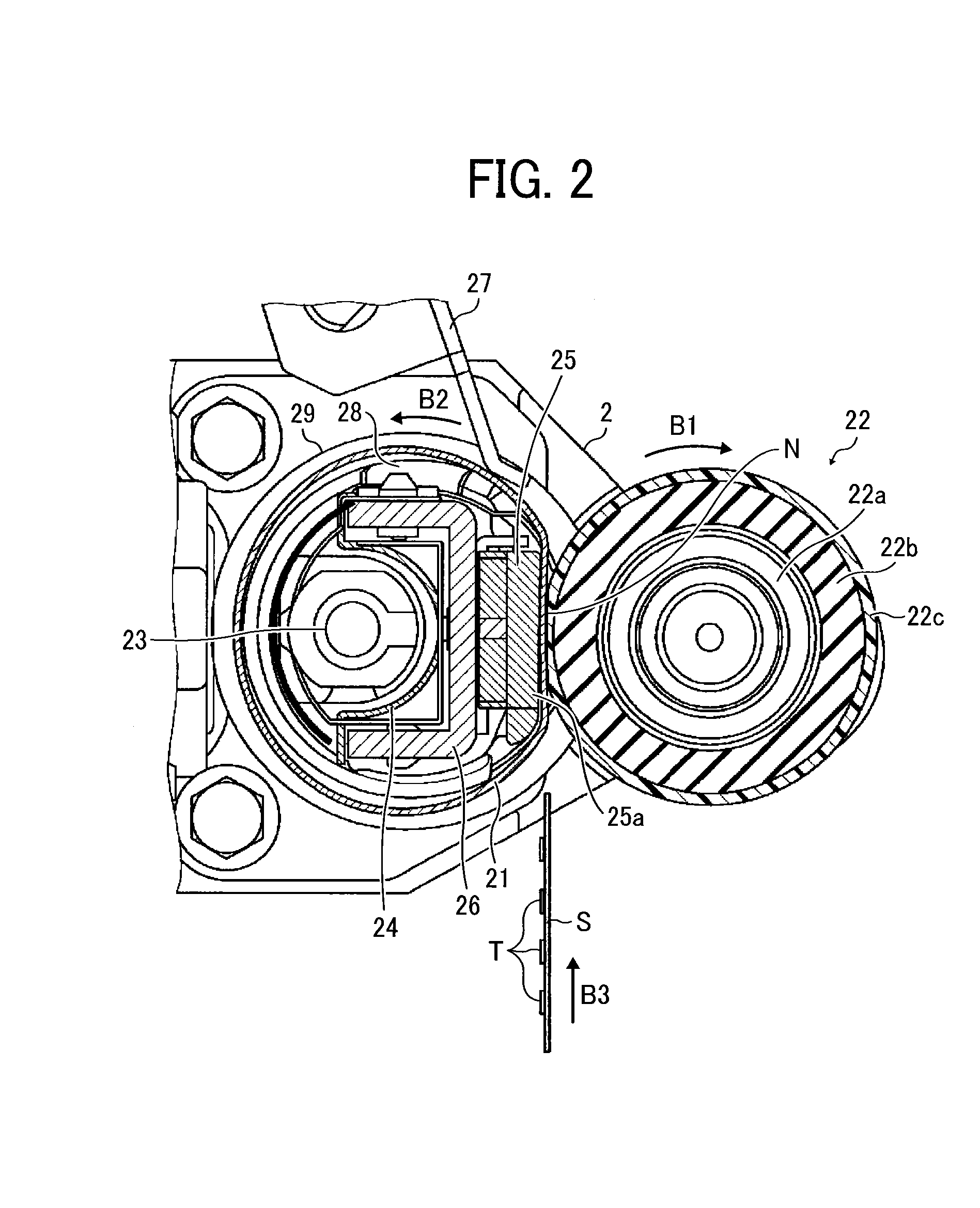
The present invention provides a new way to fix a picture onto a recording medium using heat. The device includes a rotating member, a belt that rotates against the rotating member, a part that creates a nip with the rotating member to fix the picture, and a sliding pad that keeps the belt smooth and lubricated. The sliding pad has two layers - one close to the belt and the other close to the nip creating part. The second layer has fewer fibers than the first layer.

Problems solved by technology

The on-demand type-fixing device reduces a heat capacity and upgrades effectiveness of heat transfer to the recording medium, while shortening the waiting time.
In such a fixing device, since the fixing belt is pressed against the fixing nip-forming member by the rotator and is moved with its inner circumferential surface contacting the fixing nip-forming member, the fixing belt and the fixing nip-forming member are easily worn out.
Further, when friction between the fixing belt and the fixing nip-forming member increases in the fixing device, driving motor a torque to drive the rotator accordingly increases, thereby causing the rotator to slip and be unable to drive the fixing belt in the fixing device.
As a result, the recording medium passing through the fixing nip is subjected to unstable braking and is wrinkled.
Further, once the driving motor becomes unable to bear a load, it seizes up and stops rotating,
Further still, the number of pulses inputted to the driving motor does not correspond to an actual rotation number of the driving motor resulting in a loss of synchronism
However, since vacancies in the conventional porous resin member and the sheet-like sliding member are crushed by pressure during image fixation, and accordingly, the lubricant is squeezed out, the lubricant is not retained for a long time.
At the same time, the fixing belt type-fixing device needs to be steadily and constantly driven for a long time.

Method used


Image

  • Fixing device and image forming apparatus with same
  • Fixing device and image forming apparatus with same
  • Fixing device and image forming apparatus with same

Examples


Embodiment Construction

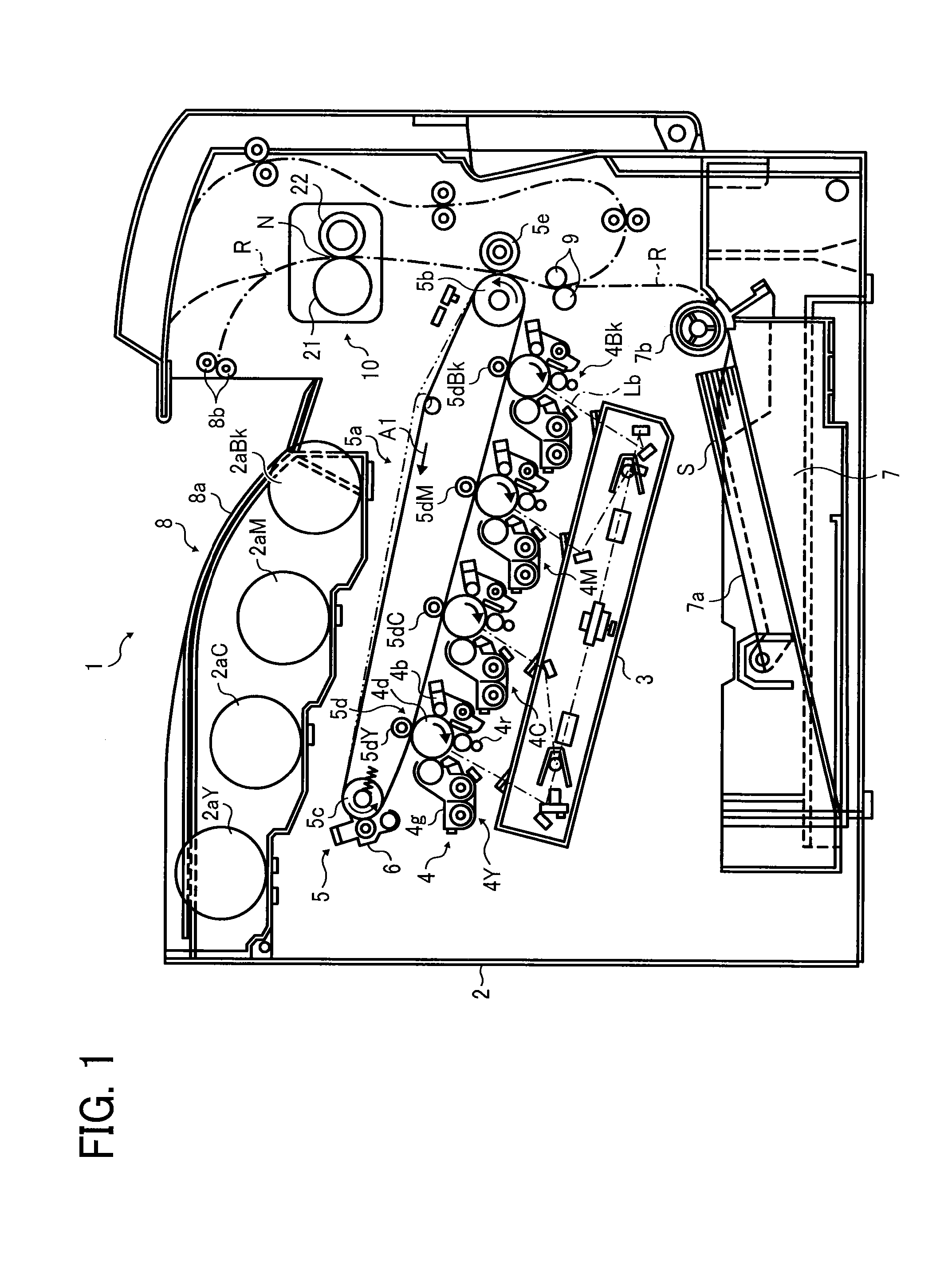
[0029]Referring now to the drawings, wherein like reference numerals designate identical or corresponding parts throughout the several views thereof and in particular to FIGS. 1 to 7, a first embodiment is initially described. Specifically, FIGS. 1 to 7 illustrate a fixing device and a color image forming apparatus as a typical example of an image forming apparatus with the fixing device according to the first embodiment of the present invention.

[0030]As shown in FIG. 1, the color image forming apparatus 1 according to this embodiment includes an apparatus body 2, an optical writing system 3, a process unit 4, a (intermediate) transferring system 5, a belt cleaning device 6, a sheet feeding device 7, a sheet exiting tray unit 8, a registration roller 9, and a fixing device 10.

[0031]The color image forming apparatus 1 includes a tandem structure configured by juxtaposing multiple photoconductive drums composed of image carriers which form color images of component colors separated to...


PUM


Abstract

A fixing device fixes an unfixed image onto a recording medium by heating the recording medium conveyed to a fixing nip. The fixing device includes a rotator, a belt rotatable by contacting the rotator, and a fixing nip-forming member provided inside a loop of the fixing belt to together form the fixing nip with the rotator via the fixing belt. A sliding pad is placed between the fixing nip-forming member and the fixing belt to retain lubricant and render the fixing belt to smoothly slide thereon. The sliding pad includes a first fibrous layer contacting the fixing belt and a second fibrous layer closer to the fixing nip-forming member than the first fibrous layer. The second fibrous layer has less fiber density than the first fibrous layer.

Description

CROSS-REFERENCE TO RELATED APPLICATIONS[0001]This patent application is based on and claims priority pursuant to 35 U.S.C. §119 to Japanese Patent Application Nos. 2013-034597, filed on Feb. 25, 2013, and 2013-265525, filed on Dec. 24, 2013, in the Japan Patent Office, the entire disclosures of which are hereby incorporated by reference herein.BACKGROUND[0002]1. Technical Field[0003]This invention relates to a fixing device and an image forming apparatus with the fixing device, and in particular, to a durable fixing device capable of fixing an unfixed image onto a recording medium and an image forming apparatus with the fixing device.[0004]2. Related Art[0005]In general, a fixing device used in an image forming apparatus, such as a copier, a facsimile, a printer, etc., includes a fixing roller heated by a heat source and a pressing roller brought in pressure contact with the fixing roller. A fixing nip is formed between the fixing roller and the pressing roller to allow a recording ...

Claims


Application Information

Patent Timeline
Patent Type & Authority Applications(United States)
IPC IPC(8): G03G15/20
CPCG03G15/2025G03G15/2053G03G2215/2035
Inventor ISHII, KENJITAKAGI, HIROMASAYOSHIURA, ARINOBU
Owner RICOH KK
Learn More