

Structure of battery unit suitable for installation of water damage sensor
a battery unit and water damage technology, applied in the field of batteries, can solve problems such as complicated connection, and achieve the effect of convenient installation and convenient operation
- Summary
- Abstract
- Description
- Claims
- Application Information
AI Technical Summary
Benefits of technology
Problems solved by technology
Method used
Image

Examples
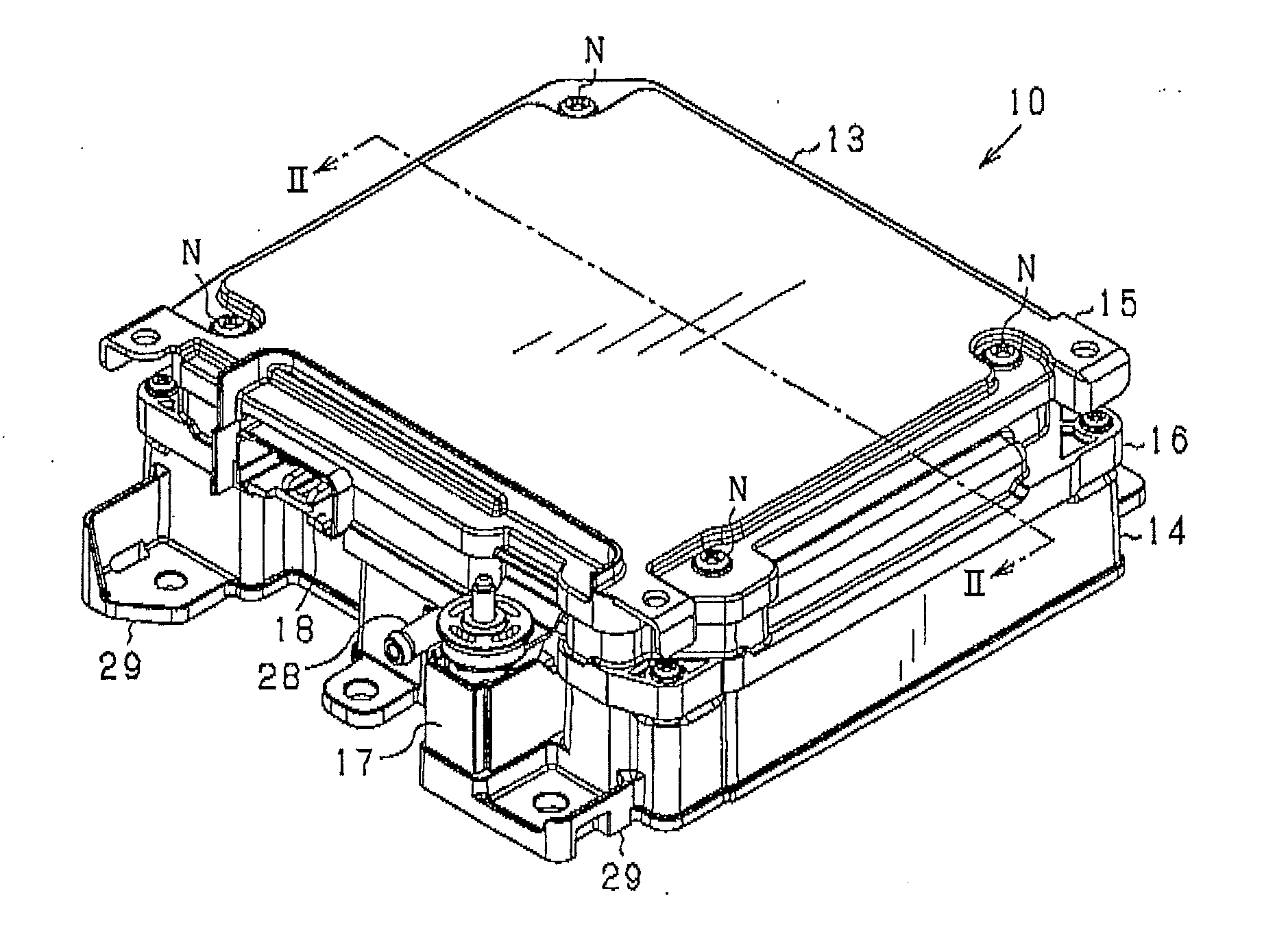
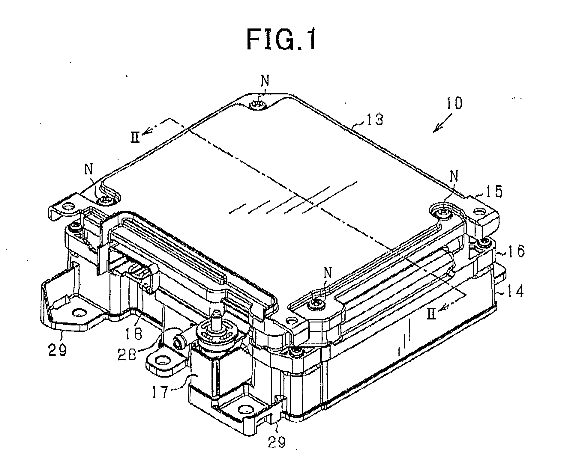
case 13
Base 14 of Storage Case 13
[0037]The base 14 of the battery unit 10 will be explained. FIG. 4 is a perspective view of the base 14. FIG. 5 is a plane view of the base 14.
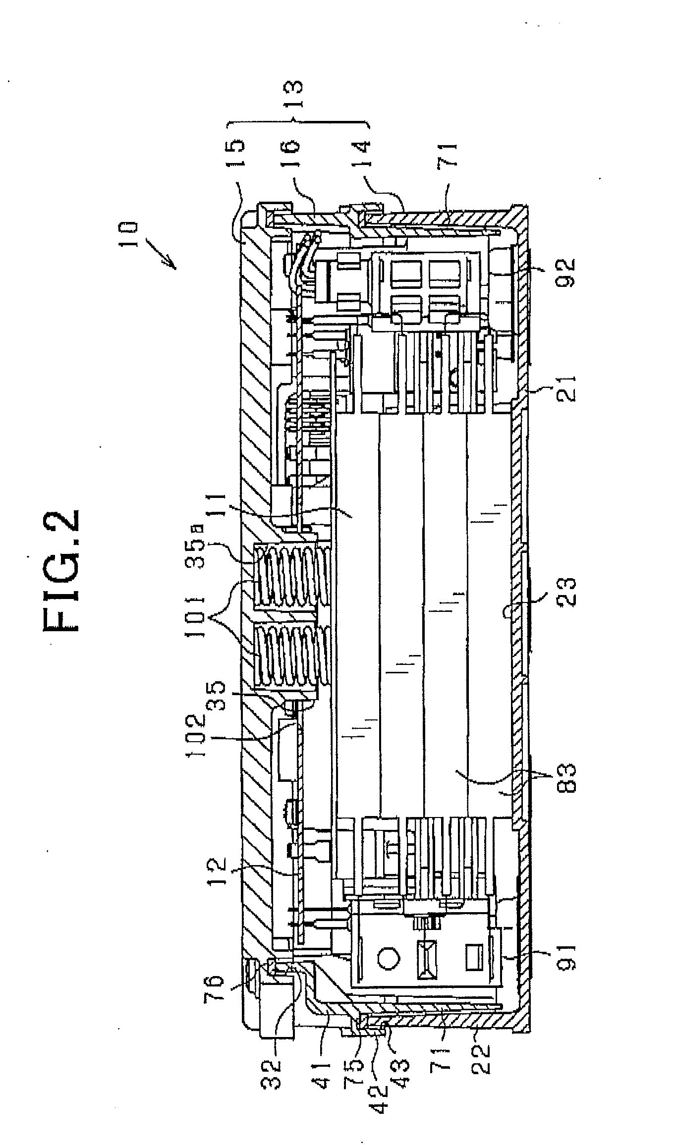
[0038]The base 14 is made from a metallic material such as aluminum and includes a bottom plate 21 and an upright wall 22 extending vertically from the bottom plate 21. The bottom plate 21 is substantially square in shape and has a circumferential edge from which the upright wall 22 extends. In other words, the upright wall 22 surrounds the circumference edge of the bottom plate 21. The bottom plate 21 serves as a module mount on which the assembled battery module 11 is retained. The upright wall 22 is so shaped as to completely encompass the assembled battery module 11 mounted on the bottom plate 21.
[0039]The base 14, as illustrated in FIG. 5, has a module mount surface 23 which is defined by a portion of a bottom wall of the base 14 and with which the assembled battery module 11 is mounted in direct contact. The mo...
case 16
Intermediate Case 16
[0052]The structure of the intermediate case 16 will be described below. FIG. 7 is a perspective view of the intermediate case 16. FIG. 8(a) is a plane view of the inter mediate case 16. FIG. 8(b) is a bottom view of the intermediate case 16. FIG. 9 is a sectional view, as taken along the line 9-9 in FIG. 8.
[0053]The intermediate case 16 is made of synthetic resin which is lower in stiffness than material of the base 14 and the cover 15. The intermediate case 16 is affixed to the base 14 and continuously extends from the upright wall 22 upward. The cover 15 is mounted on the intermediate case 16. The intermediate case 16 closes the above described square closed window, as unoccupied by both the cover 15 and the base 14.
[0054]The intermediate case 16, as illustrated in FIGS. 7, 8(a), and 8(b), has an intermediate wall 41 of a generally square closed shape. In other words, the intermediate wall 41 has a complete or unbroken side wall or circumference which defines ...
PUM
 Abstract
Description
Claims
Application Information