Methods and devices for placing a fistula device in fluid communication with a target vessel

a technology of target vessel and fistula, which is applied in the field of methods and devices for placing fistula devices in fluid communication with target vessels, can solve the problems of thinning walls, thrombosis of arterial walls, and fatty streaks that interfere with normal laminar blood flow, so as to facilitate positioning and facilitate the loading procedure. , the effect of greater control

Active Publication Date: 2005-02-10
MEDTRONIC VASCULAR INC
View PDF37 Cites 51 Cited by
  • Summary
  • Abstract
  • Description
  • Claims
  • Application Information

AI Technical Summary

Benefits of technology

[0016] The present invention seeks to alleviate the disadvantages of the known devices by providing an improved method and device for placing a conduit in fluid communication with a target vessel.
[0024] Advantageously, the fistula device includes a penetrating tip for penetrating through the wall of the heart and facilitating passage of the conduit into and through the heart wall.
[0026] Some of the prior art devices require loading of a delivery device by firstly using a puncture wire to perforate the artery wall and myocardium and then pushing the delivery system containing the fistula device e.g. shunt, stent or conduit over the puncture wire and into position. Other prior art devices have a penetrating tip to facilitate penetration of the heart wall.
[0027] However, the delivery apparatus of the present invention has the advantage that the apparatus is loaded by pulling it into position i.e. the conduit is released from the delivery apparatus by pulling the elongate cover member in a proximal direction. Delivery by using this pulling action allows for greater control of the loading procedure since the forces required to puncture the myocardium and artery wall are most easily generated in this way. This loading method also has the advantage of naturally directing the resulting blood flow from the underlying heart chamber distally, and lessens the possibility of a jet of blood impinging directly onto the artery wall. The delivery apparatus of the invention has the further advantage that it is steerable and therefore allows the fistula device to be torqued, thereby facilitating ease of positioning within the coronary artery.

Problems solved by technology

Mechanical or chemical injury of the endothelial cells or damage to their non-stick surface provides sites for thrombocyte adhesion and leads to the formation of thrombi in the arterial wall.
So called fatty streaks interfere with normal laminar blood flow, particularly at the site of blood vessel branches and bifurcations.
Sixty five percent of people with diabetes also have high blood pressure and heart disease is the most common cause of death in patients with diabetes.
If a balloon angioplasty procedure is indicated, this thinning of the walls presents two serious consequences.
Firstly, since the vessel walls are thinner, they are mechanically weaker than healthy vessels and consequently they are more likely to rupture and sustain trauma.
Although there have been recent successes through employment of endoscopic coronary artery bypass graft (ECABG) techniques, bypass surgery typically involves sternotomy, and consequently considerable trauma, pain, and associated relatively long bed residence.

Method used


Image

  • Methods and devices for placing a fistula device in fluid communication with a target vessel
  • Methods and devices for placing a fistula device in fluid communication with a target vessel
  • Methods and devices for placing a fistula device in fluid communication with a target vessel

Examples


Embodiment Construction

[0043] The following detailed description of the invention is merely exemplary in nature and is not intended to limit the invention or the application and uses of the invention. Furthermore, there is no intention to be bound by any theory presented in the preceding background of the invention or the following detailed description of the invention.

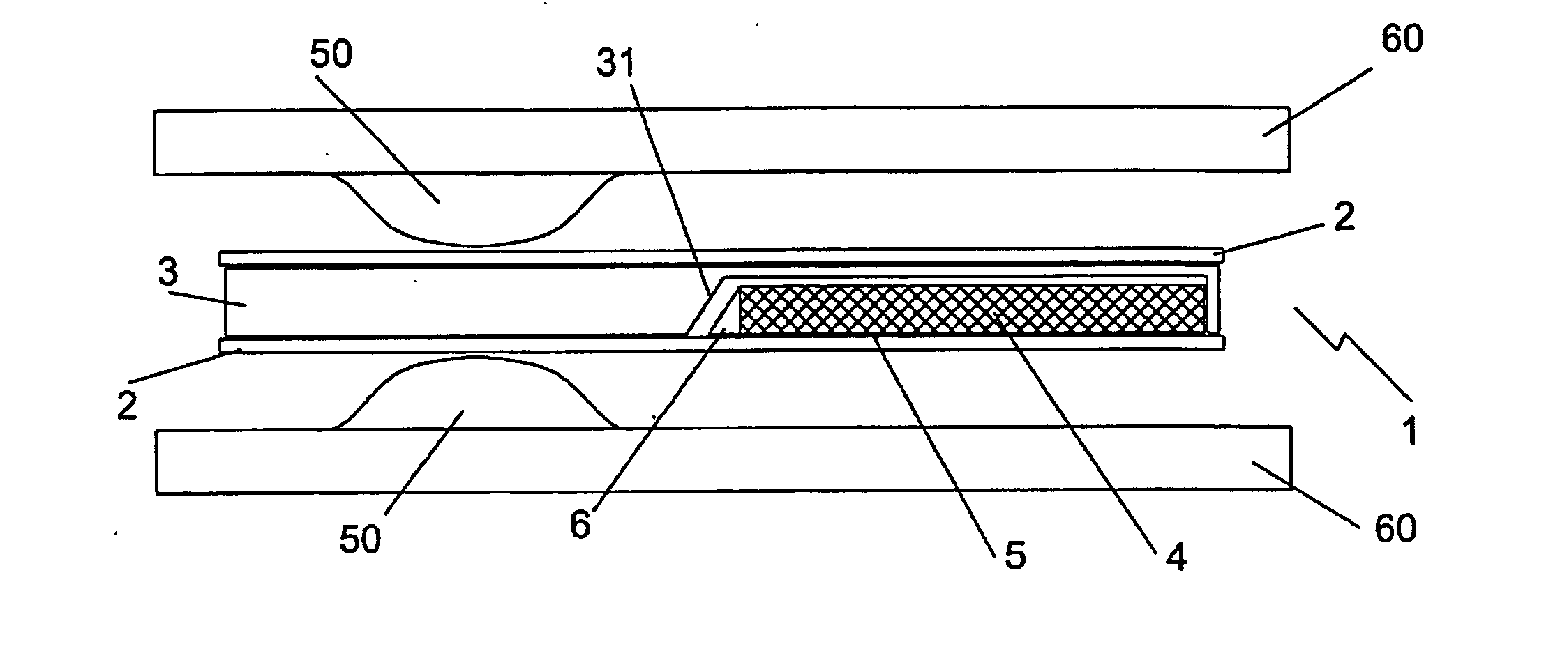
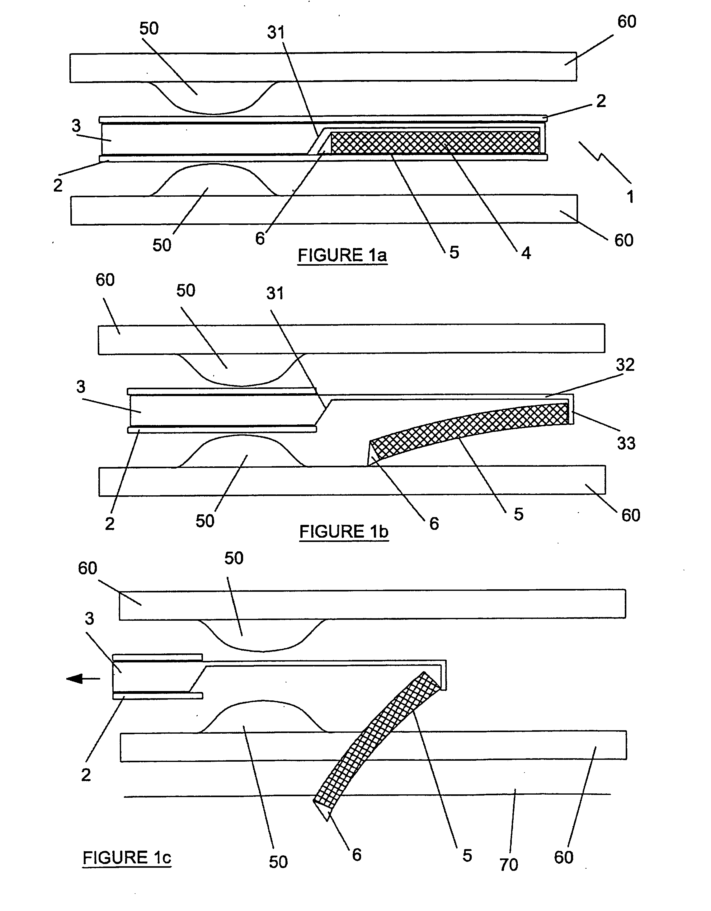
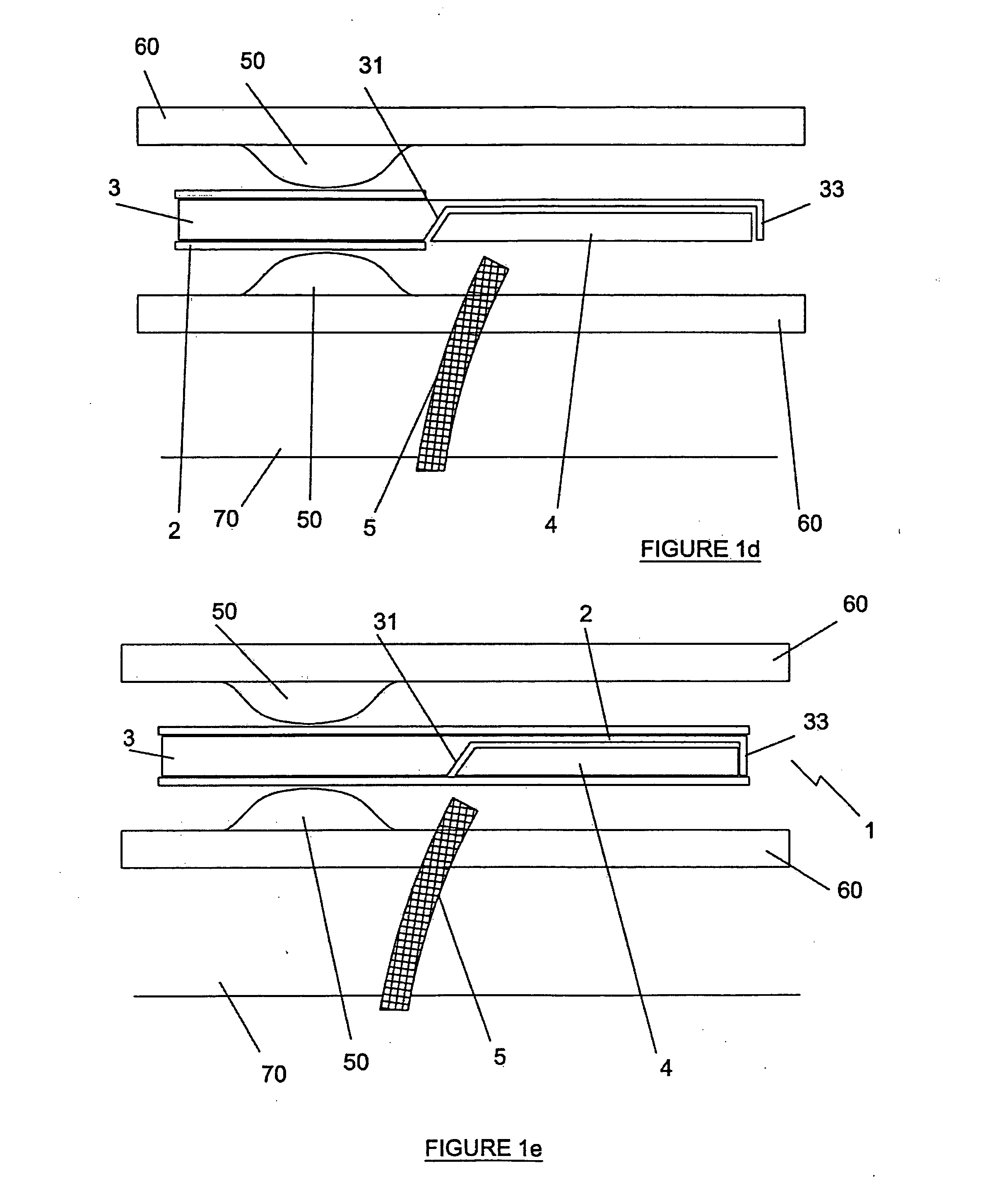
[0044] Referring to FIGS. 1(a) to 1(e) inclusive, a first embodiment of the delivery apparatus for delivering a fistula device 4 to a target vessel is indicated generally by reference number 1. The delivery apparatus 1 comprises an elongate cover member (an outer tube) 2 and an elongate support member (an inner tube) 3, as well as a fistula device 4 and a retaining sheath 5. The fistula device 4 is covered by a retaining sheath 5 which maintains the fistula device in a collapsed condition. In use, when the sheath 5 is removed, the fistula device 4 assumes an expanded condition. The fistula device 4 has a penetrating tip 6 at the proximal e...


PUM


Abstract

According to an aspect of the invention there is provided an apparatus for deploying a fistula device. The apparatus comprises an elongate cover member having a proximal end and a distal end, and an elongate support member within the cover member for supporting the fistula device and configured for relative movement with respect to the cover member so as to release the fistula device at a desired location.

Description

FIELD OF THE INVENTION [0001] The present invention concerns relates to methods and devices for placing a fistula device in fluid communication with a target vessel. The methods and devices of the invention are particularly for use in the treatment of heart disease. The term “fistula device” as used herein is to be understood to include a conduit, shunt or stent and the like. BACKGROUND OF THE INVENTION [0002] Heart disease as referred to herein is caused by the formation of atherosclerotic lesions within coronary arteries. Atherosclerosis involves changes to the intima arterial vessel wall. Atherosclerosis is characterized by a progressive accumulation of plaque about the arterial wall and associated loss of elasticity. Artery walls consist of three layers: a layer of connective tissue, a second layer of smooth muscle cells and elastic connective tissue, and a third layer of endothelial cells. The endothelial cells are flattened and elongated and they overlap and are aligned in the...

Claims


Application Information

Patent Timeline
Patent Type & Authority Applications(United States)
IPC IPC(8): A61B17/00A61F2/02A61F2/06A61F2/95
CPCA61B2017/00247A61B2018/00392A61F2/95A61F2/2493A61F2/064
Inventor CUNNIFFE, BRENDANDUFFY, NIALLCOYLE, NOELFRANCIS, RICHARD WILLIAM ALANTHORNTON, RONAN
Owner MEDTRONIC VASCULAR INC
Why Eureka
Try Eureka