

Easy-to-assemble structure of power converter
- Summary
- Abstract
- Description
- Claims
- Application Information
AI Technical Summary
Benefits of technology
Problems solved by technology
Method used
Image

Examples
first embodiment
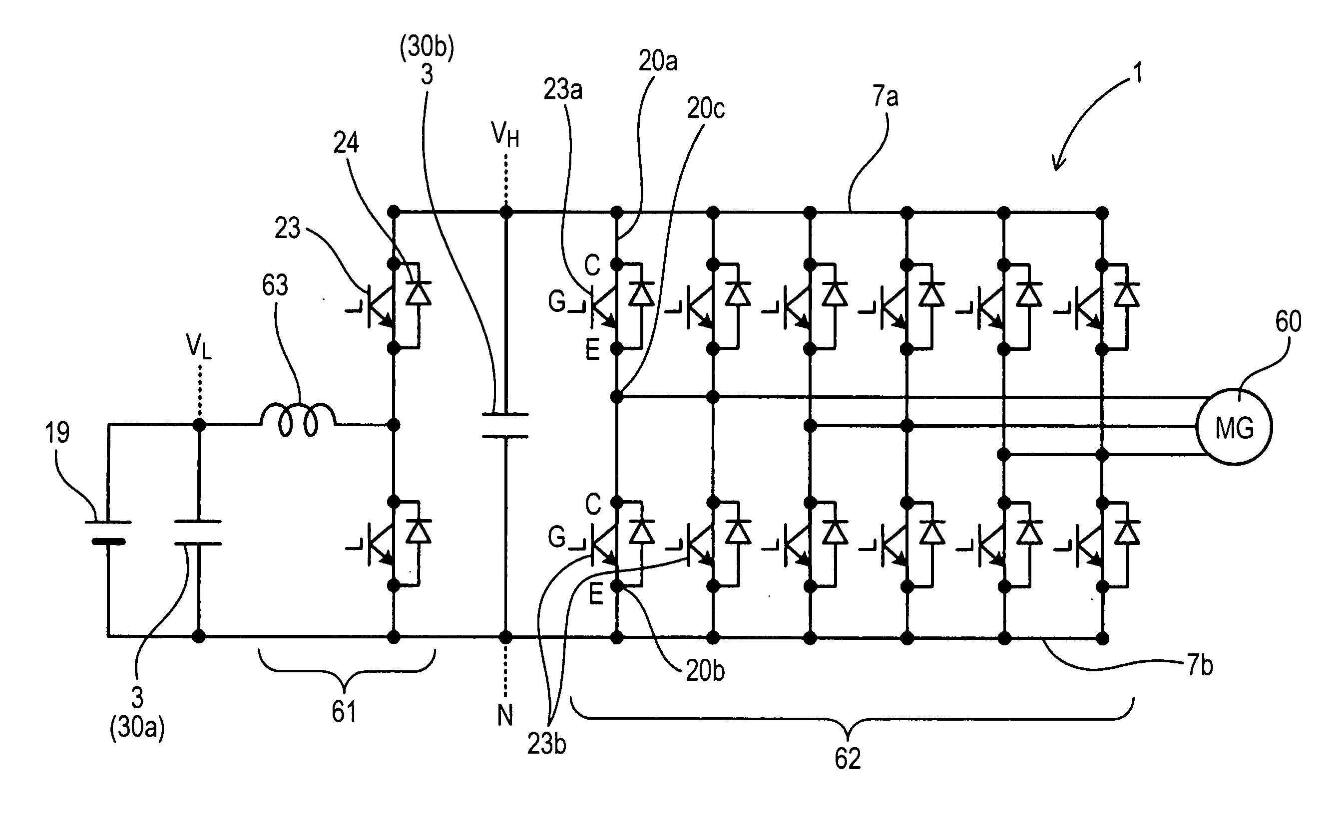
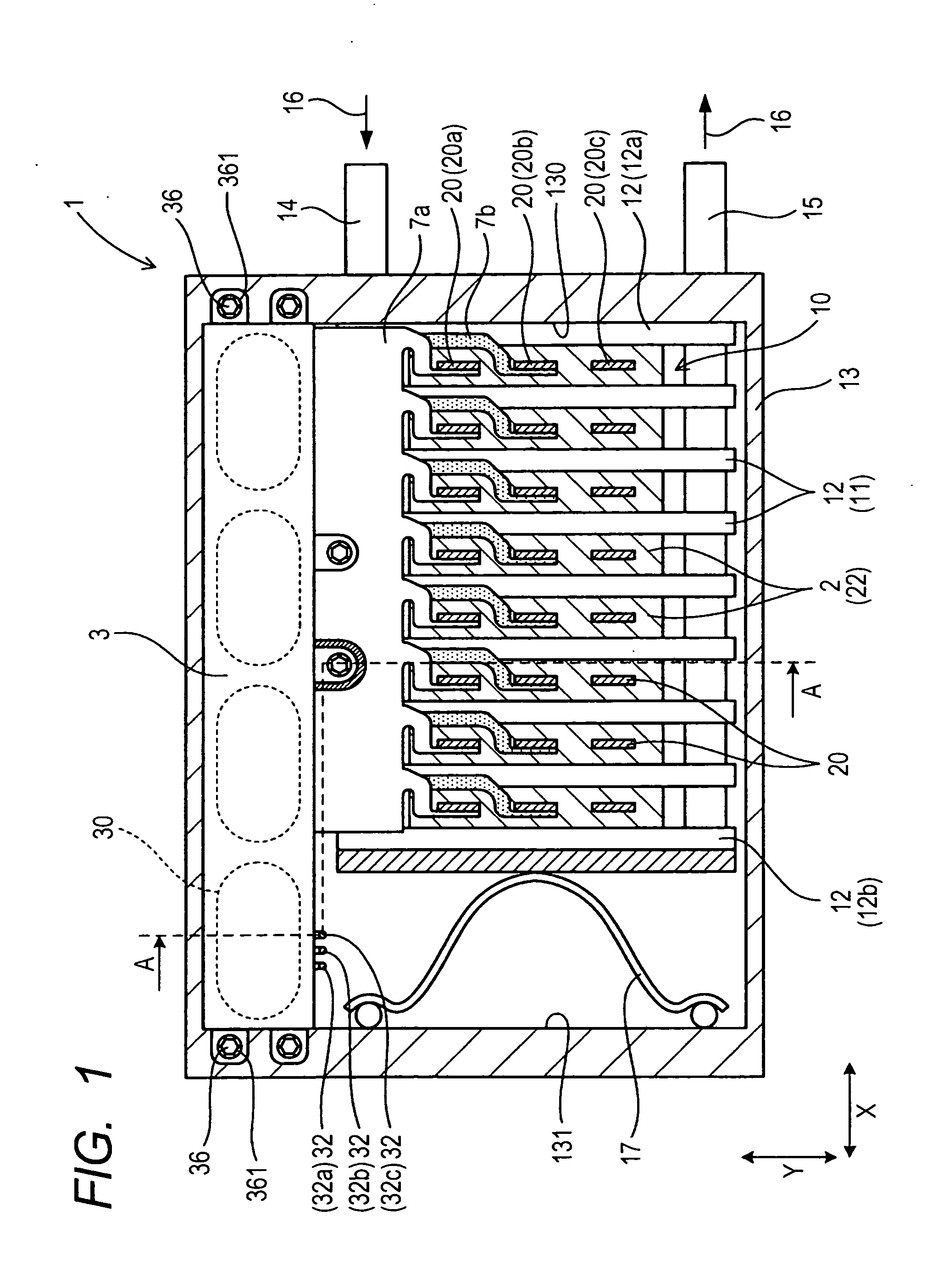
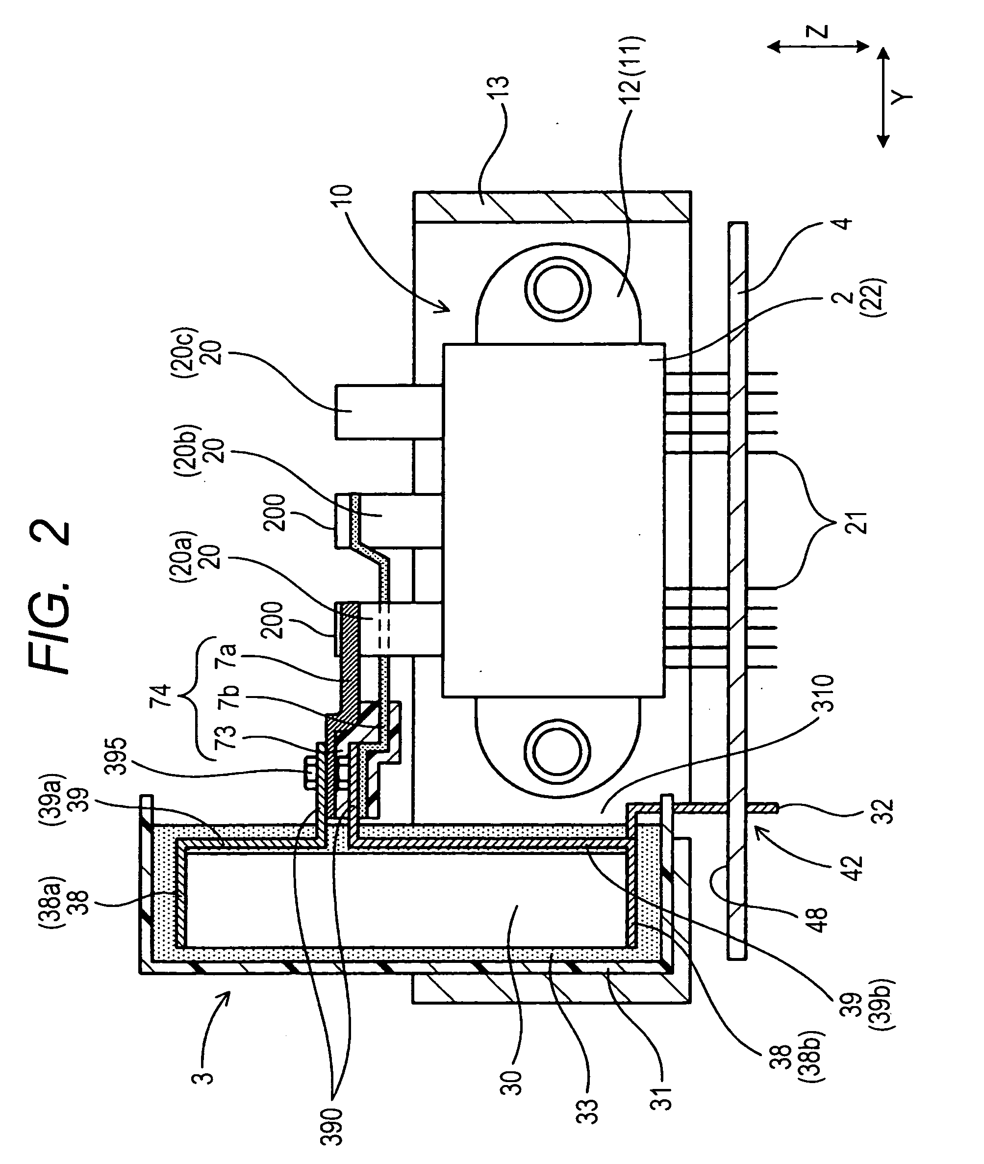
[0120]Each of the semiconductor modules 2 is, like in the first embodiment, equipped with the plurality of control terminals 21 (see FIG. 6). One of the control terminals 21 (i.e., the kelvin emitter KE of the lower-arm semiconductor device 23b) is at the same potential as the negative terminal 20b. The kelvin emitter KE (i.e., a lower-potential terminal 210) is, thus, connected to the lower-potential electrodes 38b of the capacitor devices 30 through the negative bus bar 7b, as illustrated in FIG. 2.
[0121]The capacitor 3 has the two voltage measuring terminals 32 one of which is coupled to the high potential electrode 38a of the filter capacitor device 30a, as illustrated in FIG. 5, and the other of which is coupled to the high potential electrode 38a of the main capacitor 30b.
[0122]The control circuit board 4, as clearly illustrated in FIG. 8, has formed therein two holes 45 (45a, 45b) through which the above two voltage measuring terminals 32 of the capacitor 3 pass.
[0123]The hi...
fourth embodiment
[0140]The structure of the power converter 1 of the fourth embodiment has the beneficial advantages as discussed below.
[0141]Each of the voltage measuring terminals 32 is, as already described with reference to FIGS. 13 to 15, made up of two parts: the first section 321 and the second section 322 which are welded together. This results in a decrease in production cost of the power converter 1. Specifically, it is necessary to make the voltage measuring terminal 32 to integrally include a portion (i.e., the capacitor connecting portion 71) which is to be in electric contact with the electrode of the capacitor device 30. If the voltage measuring terminal 32 is made of a one-piece strip, it will be longer than each of the first and second sections 321 and 322. For instance, when the measuring terminal 32 is cut out, as illustrated in FIG. 42, from a metal plate 70 into an L-shape, it produces a large useless portion 72. The structure of the voltage measuring terminal 32 in this embodim...
third embodiment
[0154]The structure of the voltage measuring terminal 32 of this embodiment establishes the mechanical / electrical connection of the first and second sections 321 and 322 without use of welding techniques, thus facilitating the ease of assembling of the voltage measuring terminal 32, and permits, like in the third embodiment, the first section 321 to be decreased in length to increase the area of the useless portion 72. This results in a decrease in production cost of the voltage measuring terminals 32.
[0155]The power converter 1 of the sixth embodiment also offers the same other advantages as in the first embodiment.
[0156]The power converter 1 of the seventh embodiment will be described below with reference to FIGS. 21 and 22 which is different in configuration of the voltage measuring terminals 32 from the sixth embodiment.
[0157]Specifically, the first section 321 of the voltage measuring terminal 32 has formed therein the cut-out hole 37 in which the end of the second section 322 ...
PUM
 Abstract
Description
Claims
Application Information