Energy storage device assembly

Active Publication Date: 2014-08-28
SYSTTIC POWER MFG LLC +1
View PDF7 Cites 17 Cited by
  • Summary
  • Abstract
  • Description
  • Claims
  • Application Information

AI Technical Summary

Benefits of technology

The patent text describes various aspects of an energy storage device assembly that address various problems. One technical effect is the weld bond that directly connects adjacent energy storage devices in series, providing a more stable and reliable electrical connection. Another patent describes a bus bar that engages with the projecting electrodes of two adjacent energy storage devices, providing better thermal communication and protection. The apparatus also includes a thermal bridge and elongated sleeve housing to secure and protect the energy storage devices. The housing has a contoured interior that contacts each energy storage device, allowing for improved heat transfer. Additionally, the patent describes an energy storage device assembly that includes a plurality of axially aligned energy storage devices connected at a joint by a circuit board and wiring harnesses. Overall, the patent addresses various technical issues and improves the performance and reliability of energy storage devices.

Problems solved by technology

In some cases, these forces can exceed the strength of the securing components.
In such cases, vibratory action can dislodge, rotate, wear and / or destroy portions of the devices and connections within and / or between them.
This situation can reduce the durability and lifespan of the energy storage devices.
These design choices have proven to impair the performance of energy storage devices, and can limit the opportunity to make further modifications.
This limitation can greatly increase manufacturing time and / or produce an imprecise fit, leading to faulty and / or inconsistent performance.
Attachment points according to previous designs could cause difficulty or added complexity in manufacturing processes.
In addition, a radial weld or radial interference fit can also cause attachment points between the cell and terminal to perform inefficiently or include imprecise geometrical connections.

Method used


Image

  • Energy storage device assembly
  • Energy storage device assembly
  • Energy storage device assembly

Examples


Embodiment Construction

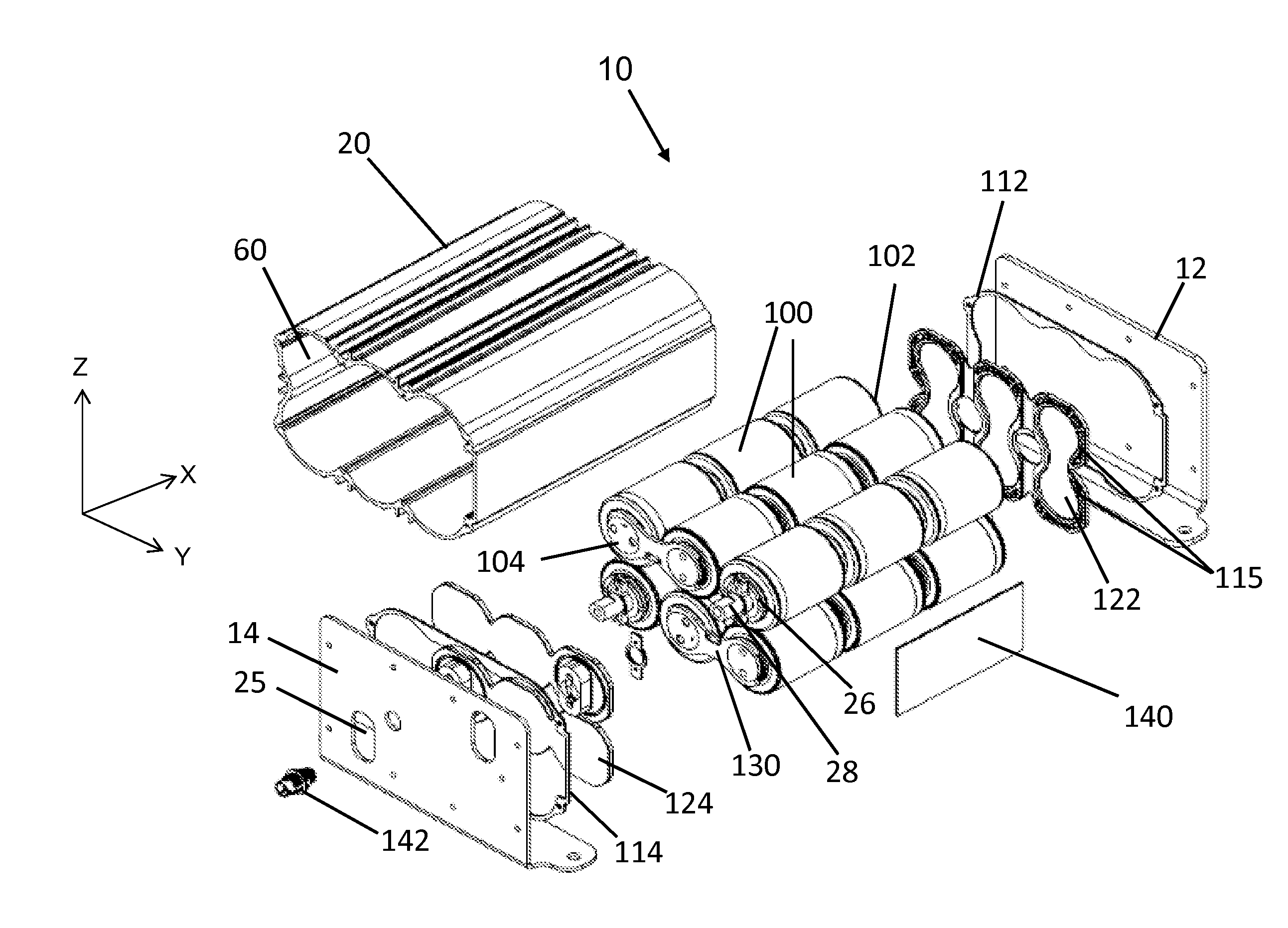
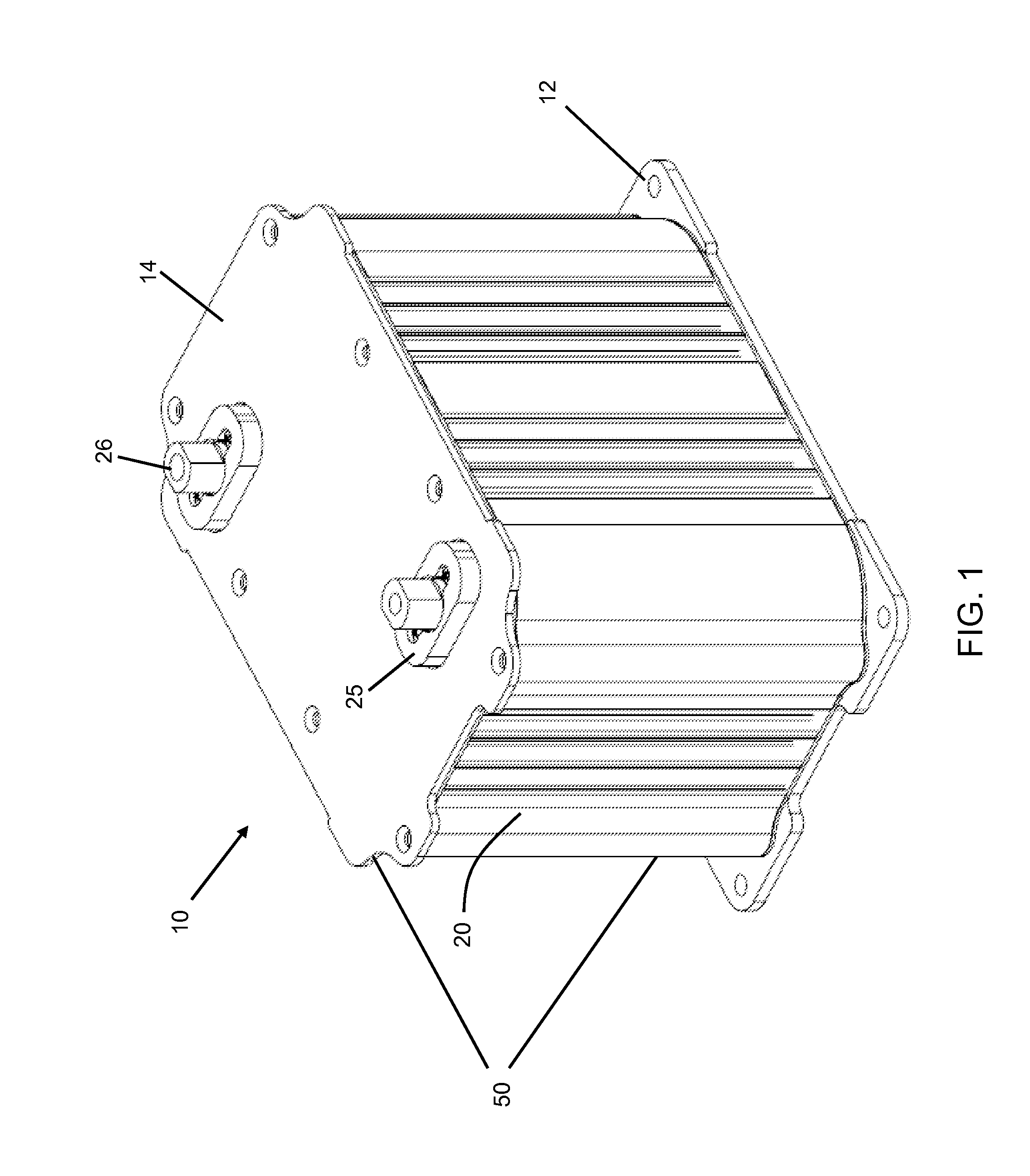
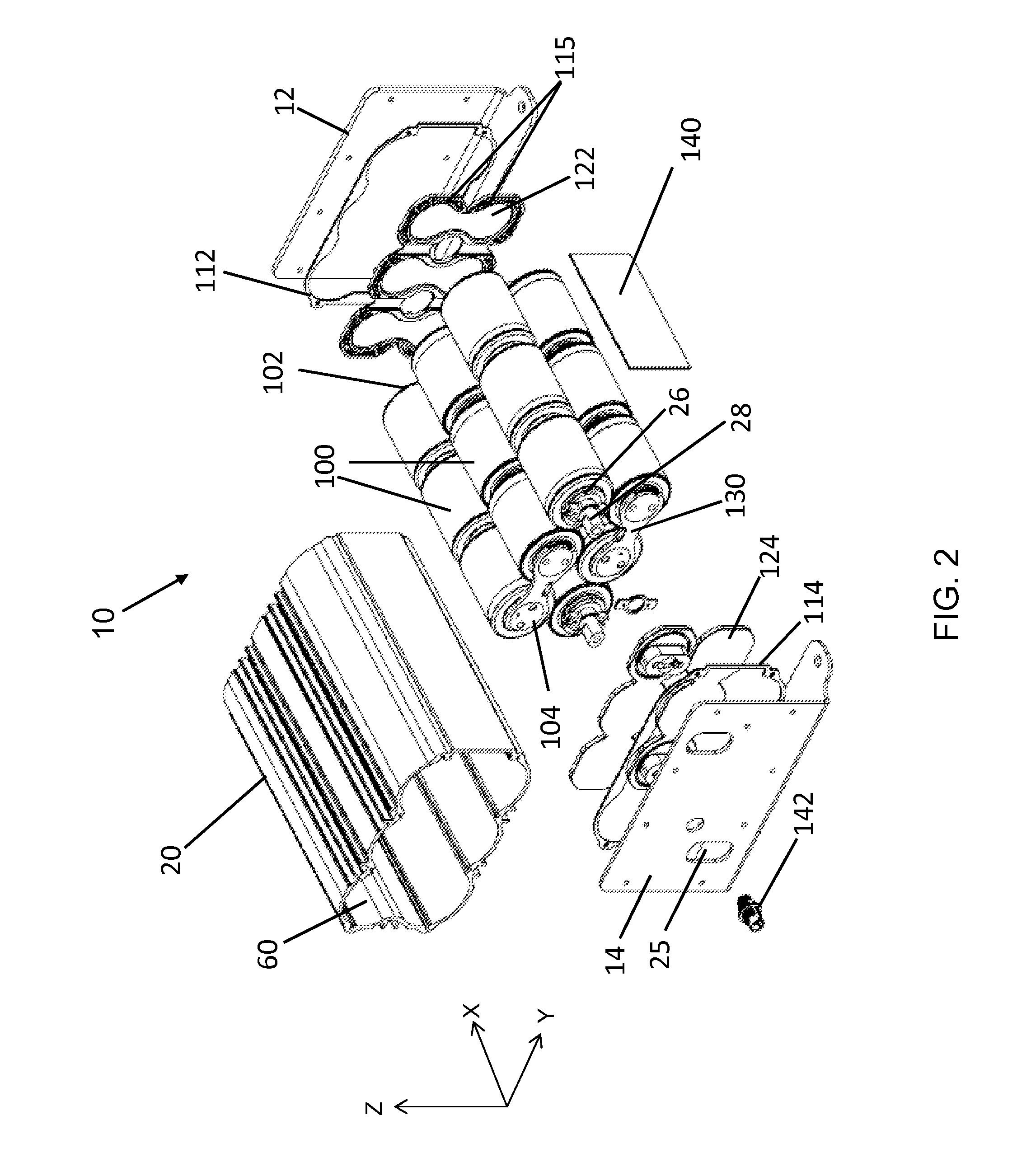
[0041]In the following description, reference is made to the accompanying drawings that form a part thereof, and in which is shown by way of illustration specific exemplary embodiments in which the present teachings may be practiced. These embodiments are described in sufficient detail to enable those skilled in the art to practice the present teachings and it is to be understood that other embodiments may be used and that changes may be made without departing from the scope of the present teachings. The following description is, therefore, merely illustrative.

[0042]When an element or layer is referred to as being “on,”“engaged to,”“disengaged from,”“connected to” or “coupled to” another element or layer, it may be directly on, engaged, connected or coupled to the other element or layer, or intervening elements or layers may be present. In contrast, when an element is referred to as being “directly on,”“directly engaged to,”“directly connected to” or “directly coupled to” another el...


PUM


Abstract

The present disclosure includes various assemblies to be used with one or more energy storage devices. In one embodiment, an energy storage device assembly can include a plurality of energy storage devices, and each of these energy storage devices can include a first projecting electrode and a second projecting electrode. The energy storage devices can be connected to each other through a weld, which can directly bond the adjacent first and second projecting electrodes of adjacent energy storage devices to one another. This configuration can allow each of the energy storage devices to be connected together in series.

Description

[0001]This application claims priority to previous U.S. Provisional Patent Application Nos. 61 / 769,937 filed Feb. 27, 2013, and 61 / 837,681 filed Jun. 20, 2013, both of which are hereby incorporated by reference.BACKGROUND OF THE INVENTION[0002]This disclosure relates generally to energy storage devices, and more particularly, to a modular assembly for one or more energy storage devices, including capacitors, ultracapacitors, and batteries.[0003]In conventional capacitor assemblies, a plurality of capacitor cells, ultracapacitor cells, batteries, or other energy storage devices are loosely held together, through securing components, within a housing that can subject the cells to a certain amount of external forces, including vibratory forces. In some cases, these forces can exceed the strength of the securing components. In such cases, vibratory action can dislodge, rotate, wear and / or destroy portions of the devices and connections within and / or between them. This situation can redu...

Claims


Application Information

Patent Timeline
IPC IPC(8): H01M2/10H05K7/20H05K7/02H01M10/655H01M50/213H01M50/224H01M50/529
CPCH01M2/1016H01M10/5044H05K7/20436H05K7/02H01M10/655Y02E60/10H01M50/529H01M50/224H01M50/213
Inventor PYZZA, JAKELAWLER, JR., ROBERT HOUSTONSADILEK, TOMASGREGORY, BRYCEPATSOS, DANIEL ALEXANDERHALBIG, DANIEL MATTHEWCORRELL, STEVE ANDREW
Owner SYSTTIC POWER MFG LLC
Why Eureka
Try Eureka