L-bead: a leak prevention system for stucco surfaces

a technology of stucco and leak prevention, applied in the field of l-bead, can solve the problems of increasing construction costs, increasing construction costs, and increasing construction costs, and reducing the possibility of leakage around windows and doors, and simplifying the smooth finish. , the effect of reducing the potential for leakag

Inactive Publication Date: 2014-09-04
E Z BEAD
View PDF3 Cites 14 Cited by
  • Summary
  • Abstract
  • Description
  • Claims
  • Application Information

AI Technical Summary

Benefits of technology

[0008]The present invention, L-Bead system, provides a system for quick, efficient and lower cost installation of stucco and or plaster which cuts down on the potential for leaks around windows and doors. The L-Bead is used as a stop between the edge of the stucco or plaster surface and the adjacent jamb or window / door frame. Proper installation of existing plaster stop requires a ¼ inch gap between the stop and the jamb, mandating the installation of a backer rod and supplemental caulking The L-Bead system eliminates this need by adding an extra plastic strip or “lip” along the edge of existing plaster stop which abuts directly to the jamb, thereby simplifying a smooth finish and minimizing the potential for leaks.

Problems solved by technology

This process that is used by some builders to prevent leaks is very time consuming.
This method of stucco installation has often resulted in leaking problems between the stucco or plaster surface and the adjacent jamb, thereby causing significant additional repair costs and frustration to both home owners and construction companies.
In addition, the extra time and materials necessary for installation of the backer rod and finishing caulk layer can add considerably to the costs and duration of the construction.

Method used


Image

  • L-bead: a leak prevention system for stucco surfaces
  • L-bead: a leak prevention system for stucco surfaces
  • L-bead: a leak prevention system for stucco surfaces

Examples


Embodiment Construction

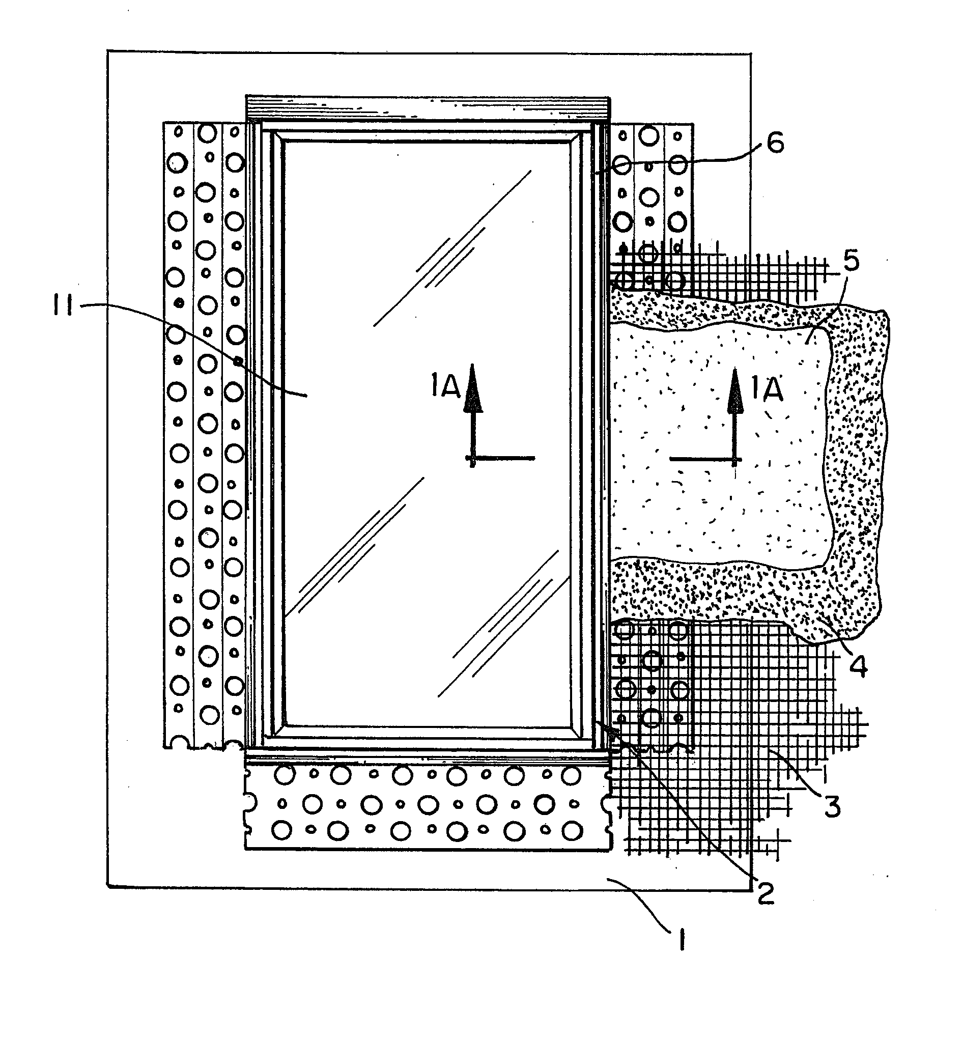
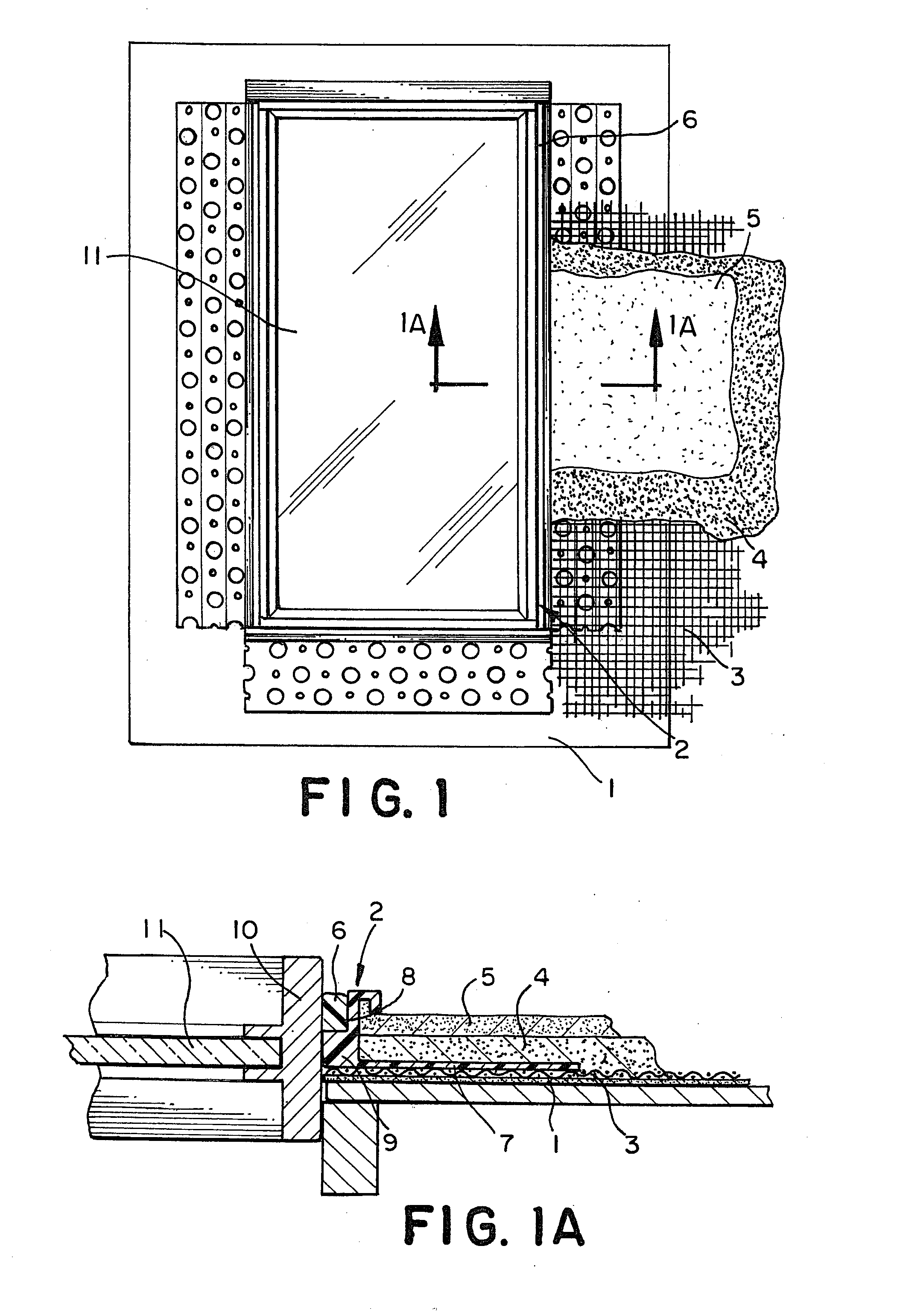
[0018]The L-Bead system significantly reduces the time and costs necessary to install smooth finishes where stucco or plaster meets window or door frames or jamb. In ordinary house of building construction, exterior and interior surfaces are often made of stucco or plaster. The method of installation of these materials is generally consistent in the construction business and usually involves the installation of a felt layer over the backing wall (plywood or similar material), a galvanized wire (or lathe) layer, and both scratch and finish coats of stucco or plaster. (See FIG. 1.)

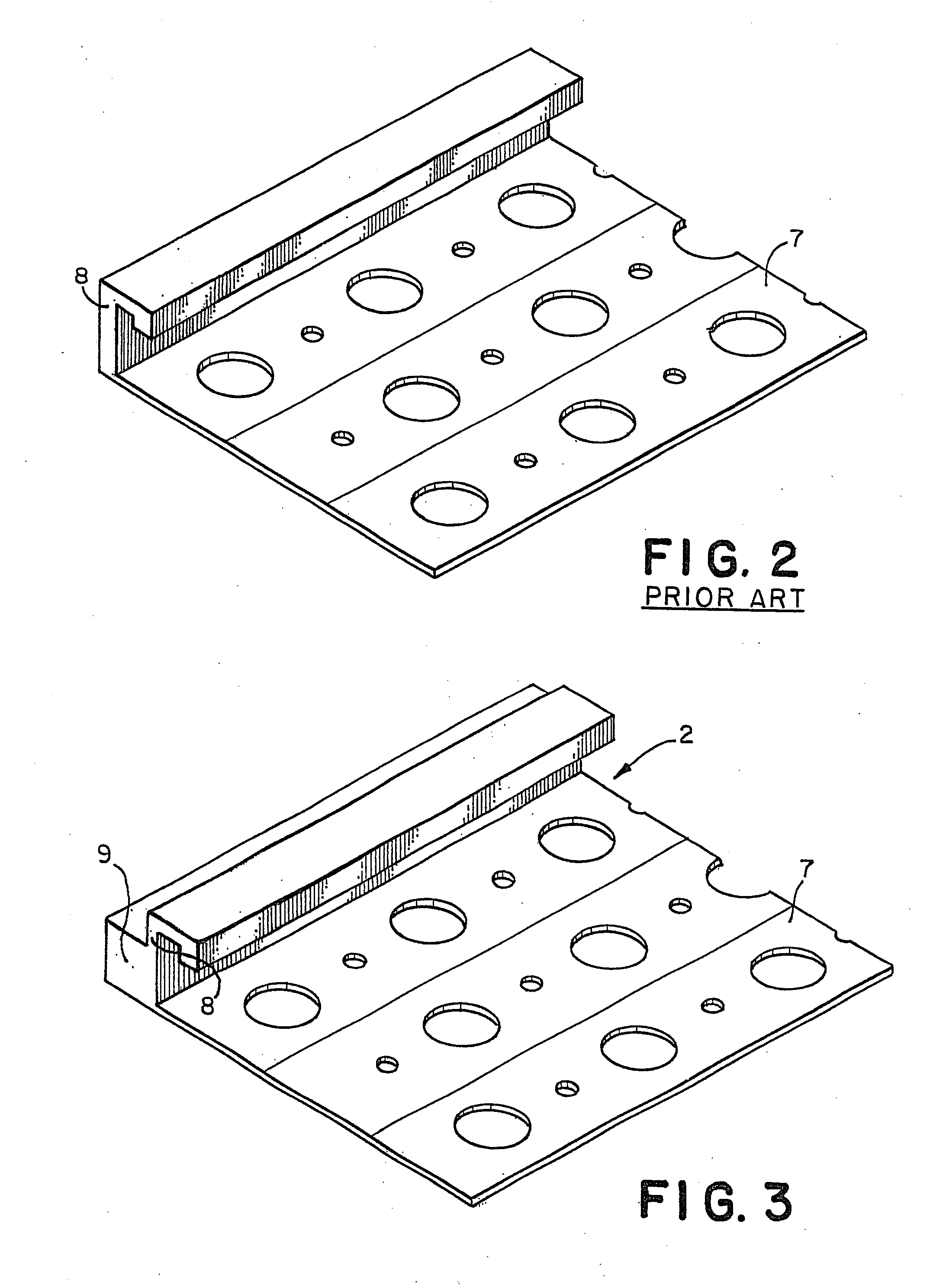
[0019]Leaking and other problems often occur where the stucco or plaster finish aligns with other design constructs of the home or building, such as windows or doors. Stop strips which contain and form the outer boundaries of the stucco or plaster surfaces where they meet window or door jambs have been developed to improve the seal and finishes of these adjacencies. In particular, the use of standard plaster...


PUM

PropertyMeasurementUnit
widthaaaaaaaaaa
distanceaaaaaaaaaa
areaaaaaaaaaaa

Abstract

A stop bead for mounting along a frame or jamb of a window or door of a building to separate the frame or jamb from plaster or stucco material during application of the plaster or stucco material to the building comprises a first side end portion and a second side end portion, the first side portion having a leading edge for engaging the frame or jamb when the stop bead is mounted adjacent to the frame or jamb, a base panel having a front face, a stop bead wall formed on the base panel and extending outwardly above the front face of the base panel, the stop bead wall having an engaging surface for engaging plaster or stucco and a frame / jamb facing surface that faces the frame or jamb when the stop bead is mounted adjacent to the frame or jamb, and a spacing member formed on the stop bead and extending outwardly away from the frame / jamb facing surface of the stop bead wall for spacing the stop bead wall a predetermined distance from the frame or jamb when the stop bead is mounted adjacent to the frame or jamb, the spacing member forming the leading edge of the first side portion of the stop bead and forming gap between the stop bead wall and the frame or jamb when the stop bead is mounted adjacent to the frame or jamb for receiving caulk for sealing between the stop bead and the frame or jamb. In a preferred embodiment, the spacing member is flexible to permit movement of the spacing member responsive to movement to weather induced movement of the jamb after the stop bead is mounted adjacent to the jamb.

Description

CROSS REFERENCES TO RELATED APPLICATIONS[0001]This application is a continuation of U.S. patent application Ser. No. 12 / 152,046, which is a continuation-in-part of U.S. patent application Ser. No. 11 / 259,499, which is a divisional application of U.S. patent application Ser. No. 09 / 952,920. This application also is related to U.S. patent application Ser. No. 11 / 981,421, which is a divisional application of U.S. patent application Ser. No. 11 / 259,499, which is a divisional application of U.S. patent application Ser. No. 09 / 952,920. U.S. patent application Ser. Nos. 12 / 152,046, 11 / 259,499, 09 / 952,920, and 11 / 981, 421 are incorporated herein by reference.BACKGROUND OF THE INVENTION[0002]1. Field of the Invention[0003]This invention relates to the application of stucco or plaster in homes or other buildings and specifically to the stop system used between the edge of the stucco or plaster surface and the adjoining frame for windows and doors or where stucco or plaster meets any material ...

Claims


Application Information

Patent Timeline
Patent Type & Authority Applications(United States)
IPC IPC(8): E06B1/62E04F13/04E04B1/66E06B1/04E04F17/08
CPCE06B1/62E04B1/66E04F13/045E06B1/04E04F17/08E06B2001/624E04F19/0495E04F13/06E04F19/02E06B7/23E06B7/22E06B1/02
Inventor MAZIARZ, JEFFREY
Owner E Z BEAD
Why Eureka
Try Eureka