Swinging motion reducing apparatus and ship using the same

a technology of reducing apparatus and swinging motion, which is applied in the direction of instruments, special-purpose vessels, vessel construction, etc., can solve the problems of reducing the gimbal is swung violently, and the mechanism that makes the swinging motion reducing apparatus stop urgently in an emergency situation, etc., to achieve the effect of improving the safety of the apparatus

Active Publication Date: 2014-09-04
TOHMEI IND CO LTD
View PDF9 Cites 14 Cited by
  • Summary
  • Abstract
  • Description
  • Claims
  • Application Information

AI Technical Summary

Benefits of technology

[0010]An object of the present invention is to provide a swinging motion reducing apparatus which can stop urgently in a short period of time and a ship using the same. Another object of the present invention is to provide a swinging motion reducing apparatus which can further improve its safety and a ship using the same. Still another object of the present invention is to provide a swinging motion reducing apparatus which can easily confirm its swinging motion reducing effect and a ship using the same.
[0018]According to the present invention, the swinging motion reducing apparatus which can stop urgently in a short period of time and the ship using the same can be provided. In addition, according to the present invention, the swinging motion reducing apparatus which can further improve its safety and the ship using the same can be provided. Furthermore, according to the present invention, the swinging motion reducing apparatus which can easily confirm its swinging motion reducing effect and the ship using the same can be provided.

Problems solved by technology

However, mechanisms that make the swinging motion reducing apparatus stop urgently in an emergency are not provided.
Therefore, for example, in the case that the braking device is in malfunction in which the braking device cannot fulfill its function due to the temperature increase, there is the potential that the gimbal is swung violently and the swinging motion reducing apparatus breaks down.
However, it takes long time to completely stop the flywheel.
If the swinging motion reducing apparatus is left for a long time when the braking device is in malfunction, since the gimbal operates continuously for a long time while the braking device still remain in malfunction, there is the potential for causing the braking device to break down.
Then, after turning off the power switch, it is necessary to wait for completely stopping of the swinging motion reducing apparatus for a long time.
However, since a situation of waves that the ship body receives may be varied, it is difficult to confirm the effect of the swinging motion reducing apparatus under an equivalent wave condition as an input to the ship body.
In addition, it is difficult to experience the effect of the swinging motion reducing after a long time passing.

Method used


Image

  • Swinging motion reducing apparatus and ship using the same
  • Swinging motion reducing apparatus and ship using the same
  • Swinging motion reducing apparatus and ship using the same

Examples


Embodiment Construction

[0025]A swinging motion reducing apparatus and a ship using the same according to an embodiment of the present invention will be described below referring to the accompanying drawings.

[0026]First, the configurations of the swinging motion reducing apparatus and the ship using the same according to the present embodiment will be described.

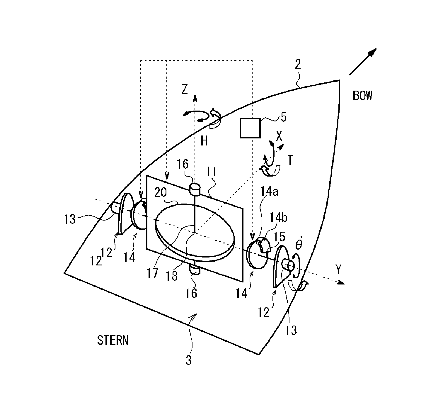
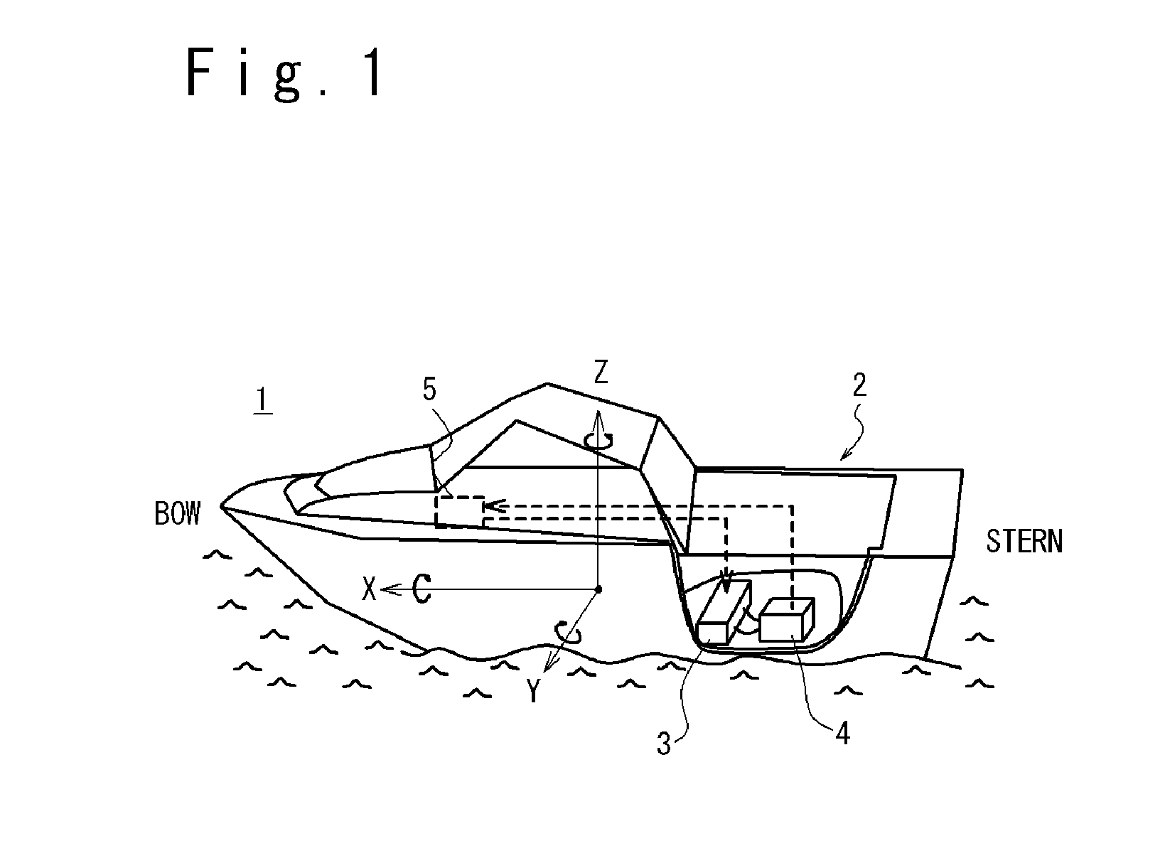
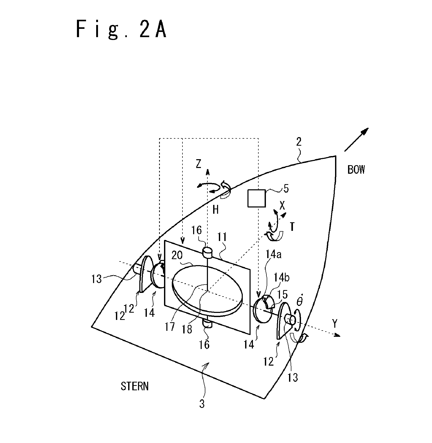
[0027]FIG. 1 is a schematic diagram illustrating the configuration of the ship using the swinging motion reducing apparatus according to the present embodiment. Here, a boat is shown as an example of a ship 1. However, the swinging motion reducing apparatus according to the present embodiment can be applied to not only a boat but also other kinds of ships, by changing its size and arrangement corresponding to a kind of ship. The ship 1 includes: a ship body 2, a swinging motion reducing apparatus 3, a generator 4, and a control device 5.

[0028]The swinging motion reducing apparatus 3 is installed in the ship body 2 and fixed inside the ship body 2. T...


PUM


Abstract

A swinging motion reducing apparatus includes a flywheel 20, a gimbal 11, a gimbal supporting section 12, a damper 13 and a lock mechanism 14. The gimbal 11 rotatably supports the flywheel 20. The gimbal supporting section 12 supports the gimbal 11 through a gimbal shaft 15 such that the gimbal 11 can swing. The damper 13 brakes a swinging motion of the gimbal 11. The lock mechanism 14 locks a swinging motion of the gimbal 11.

Description

TECHNICAL FIELD[0001]The present invention relates to a swinging motion reducing apparatus which suppressing a swinging motion and a ship using the same.BACKGROUND ART[0002]A swinging motion reducing apparatus is known, which reduces a swinging motion of a moving apparatus such as a ship. For example, Japanese patent publication JP Heisei 7-215280 A (corresponding to U.S. Pat. No. 5,628,267 A) discloses a ship oscillation suppression device and a ship. This ship oscillation suppression device has a control moment gyro (100). In the oscillation suppression device, a spin shaft (60) of a flywheel (1) of the gyro (100) is driven by a flat type spin motor (5) and is supported by a gimbal (2) through spin bearings (6). The gimbal (2) is supported by supports (8) through gympal shafts (3) and gimbal bearings (7). The oscillation of the gimbal shaft (3) is braked by disk brakes (30). The disk brake (30) includes a gimbal shaft connection fixing disk (9) and a support connection fixing disk...

Claims


Application Information

Patent Timeline
Patent Type & Authority Applications(United States)
IPC IPC(8): G01C19/04B63B39/04
CPCG01C19/04B63B39/04Y10T74/1257
Inventor NOHARA, TSUYOSHITAKEUCHI, HIROSHIUMEMURA, KATSUYA
Owner TOHMEI IND CO LTD
Why Eureka
Try Eureka