Trigger assembly

a technology of trigger assembly and trigger, which is applied in the direction of compressed gas guns, white arms/cold weapons, and weapons components, etc., can solve the problems of relatively high trigger pull effort or load, inadvertent activation of the firing mechanism, and relatively high trigger effort in the prior ar

Active Publication Date: 2014-09-04
2360216 ONTARIO
View PDF6 Cites 37 Cited by
  • Summary
  • Abstract
  • Description
  • Claims
  • Application Information

AI Technical Summary

Benefits of technology

[0016]In another aspect, the captured roller is elongate and at least partially defines a central axis thereof. The captured roller is mounted in the housing for rotation of the captured roller about the central axis and for movement of the captured roller in ...

Problems solved by technology

If the trigger pull load required is relatively large, then an inadvertent activation of the firing mechanism is unlikely.
However, the typical trigger mechanism has a number of deficiencies.
However, known triggers rely on friction between the ticker (or trigger) and sear surfaces and as a result they have relatively high trigger pull efforts or loads, e.g., in the range of approximately 2.5 lbs. to approximately 9 lbs.
Some manufacturers have attempted to use leverage (i.e., by changing the geometry of the conventional trigger mechanism) to lower forces between ticker ...

Method used


Image

  • Trigger assembly
  • Trigger assembly
  • Trigger assembly

Examples


Embodiment Construction

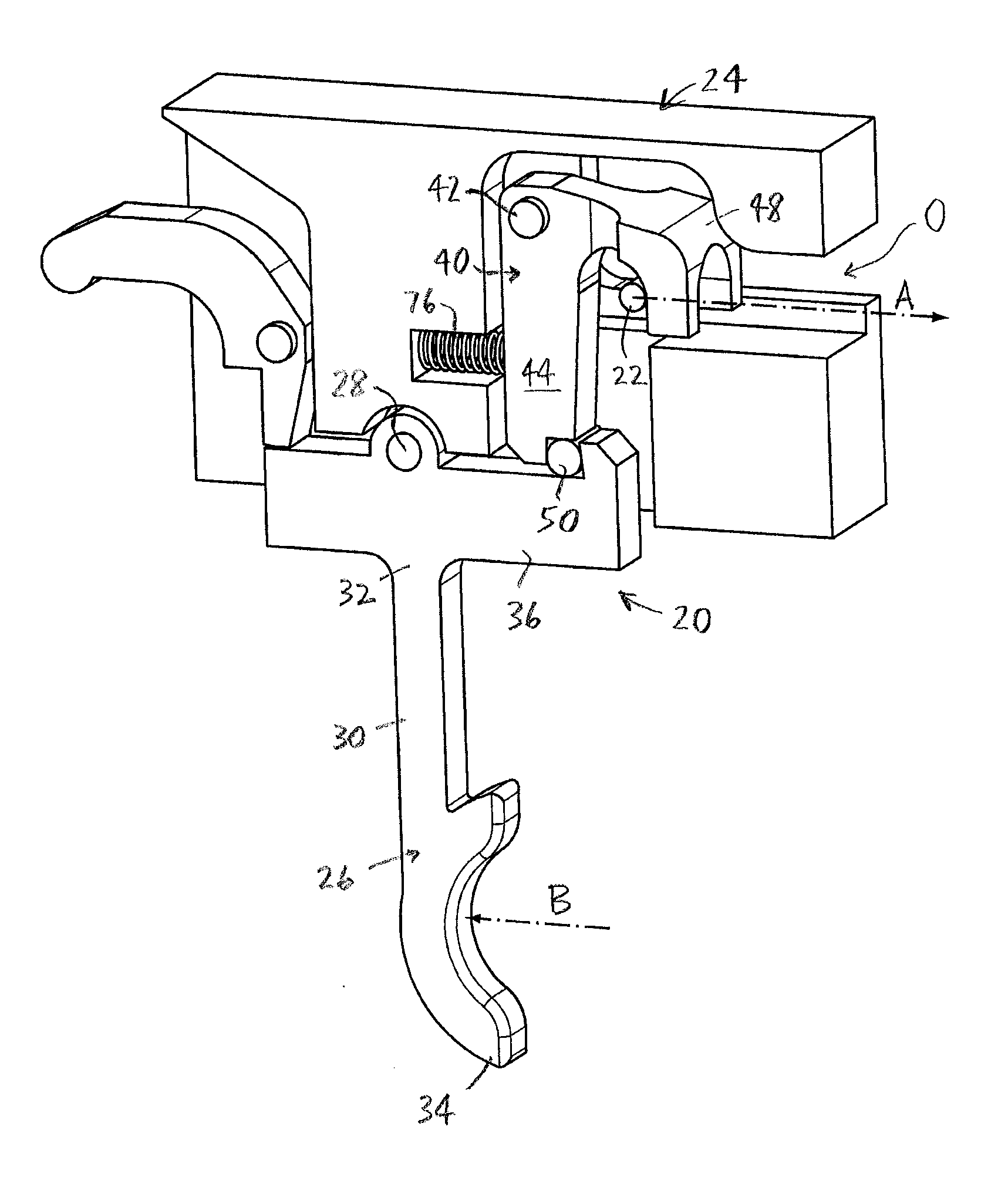
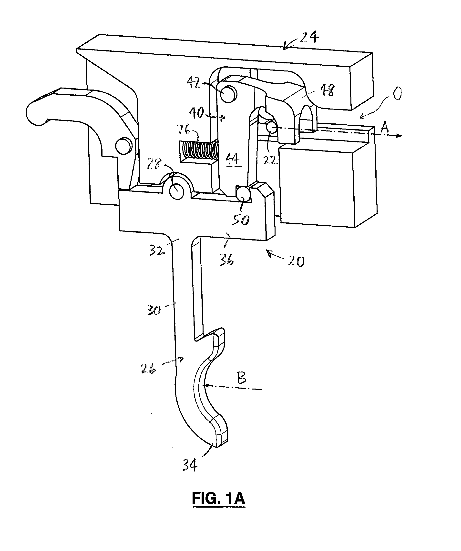
[0044]In the attached drawings, like reference numerals designate corresponding elements throughout. Reference is first made to FIGS. 1A-11 to describe an embodiment of a trigger assembly of the invention referred to generally by the reference numeral 20. As will be described, the trigger assembly 20 is for activating a firing mechanism 22. Preferably, the trigger assembly 20 is mountable in a housing 24. In one embodiment, the trigger assembly 20 preferably includes a trigger 26 pivotally mounted on a trigger pivot pin 28. It is preferred that the trigger 26 includes an elongate trigger arm 30 extending between a top end 32 proximal to the trigger pivot pin 28, and a bottom end 34 distal to the trigger pivot pin 28. The trigger 26 preferably also includes a sear arm 36 positioned transverse to the trigger arm 30, the sear arm 36 having a first sear surface 38 (FIGS. 3, 8). As can be seen in FIGS. 1A and 2-7B, the trigger assembly 20 preferably also includes a firing element 40 pivo...


PUM


Abstract

A trigger assembly for activating a firing mechanism. The trigger assembly includes a trigger having a sear arm with a first sear surface, and a firing element including a body portion with a second sear surface and an engagement portion for engagement with the firing mechanism, for activating the firing mechanism. The trigger assembly also includes a captured roller positioned for engagement with the first and second sear surfaces. The trigger is pivotable between a load position, in which the captured roller is held between the first and second sear surfaces, and a release position, in which the second sear surface is disengaged from the captured roller and the firing element is released. The firing element is pivotable between a first position, in which the firing element is held by the captured roller, and a second position, in which the firing element is disengaged from the captured roller.

Description

CROSS-REFERENCE TO RELATED APPLICATION[0001]This application claims the benefit of U.S. Provisional Patent Application No. 61 / 614,784, filed on Mar. 23, 2012, the disclosure of which is hereby incorporated fully herein by reference.FIELD OF THE INVENTION[0002]The present invention is a trigger assembly for activating a firing mechanism.BACKGROUND OF THE INVENTION[0003]Many known devices include a firing mechanism activatable by movement of a trigger. The devices are typically for firing or launching a projectile. Typically, the trigger is moved by imposing a trigger pull load on the trigger, to cause the trigger to move from a loaded position, at which the firing mechanism is activatable, to a released position, at which the firing mechanism is activated. Activation of the firing mechanism is conventionally effected in various ways, e.g., via release of an element of the firing mechanism, or otherwise initiating movement of an element of the firing mechanism. As is well known in the...

Claims


Application Information

Patent Timeline
IPC IPC(8): F41A19/10F41B5/12
CPCF41B5/12F41A19/10F41A17/46F41A19/12F41A19/17F41A19/42F41A19/25F41B5/1469
Inventor LIPOWSKI, MATS
Owner 2360216 ONTARIO
Why Eureka
Try Eureka