Process for manufacturing a seamless tube

a manufacturing process and seamless technology, applied in the direction of manufacturing tools, metal rolling arrangements, rolling mill drives, etc., can solve the problems of increasing the rotary forging effect at the time of gripping the billet by the rolls, increasing the shearing deformation, and preventing the rotary forging effect and/or shearing deformation. , to achieve the effect of preventing the thickness deviation, preventing the miss-rolling, and preventing the effect of rolling

Active Publication Date: 2009-03-12
NIPPON STEEL CORP
View PDF6 Cites 10 Cited by
  • Summary
  • Abstract
  • Description
  • Claims
  • Application Information

AI Technical Summary

Benefits of technology

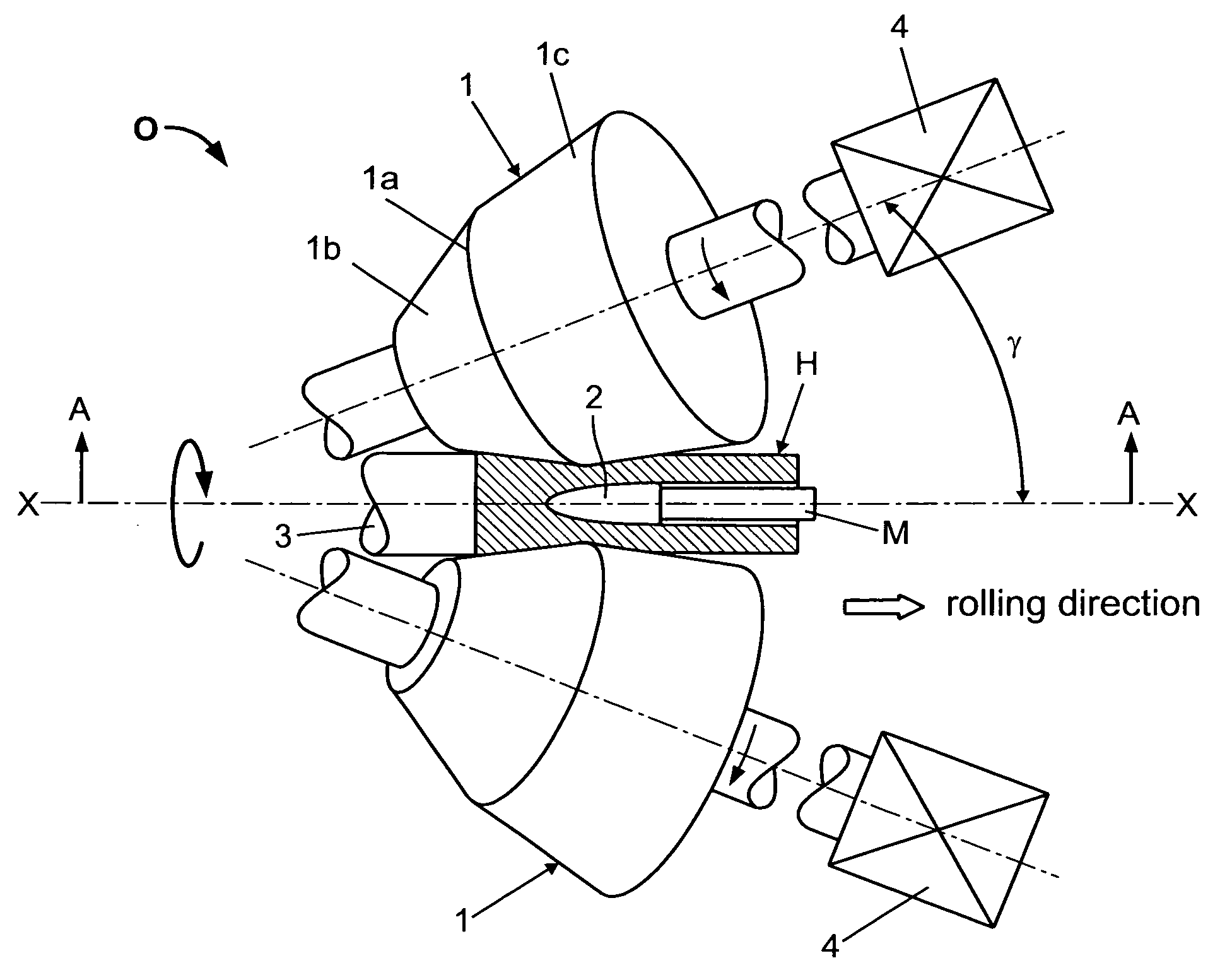
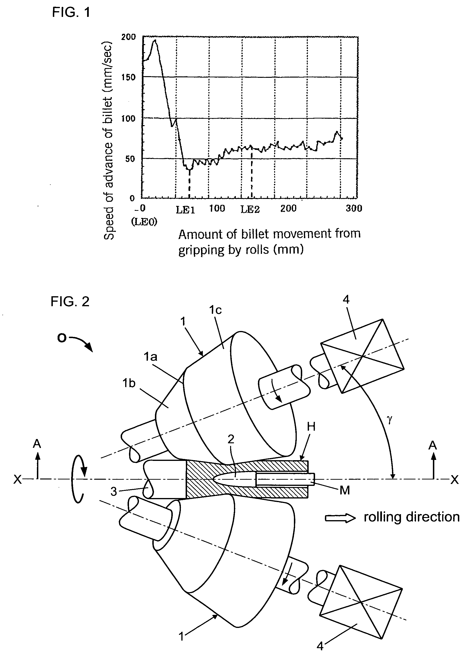
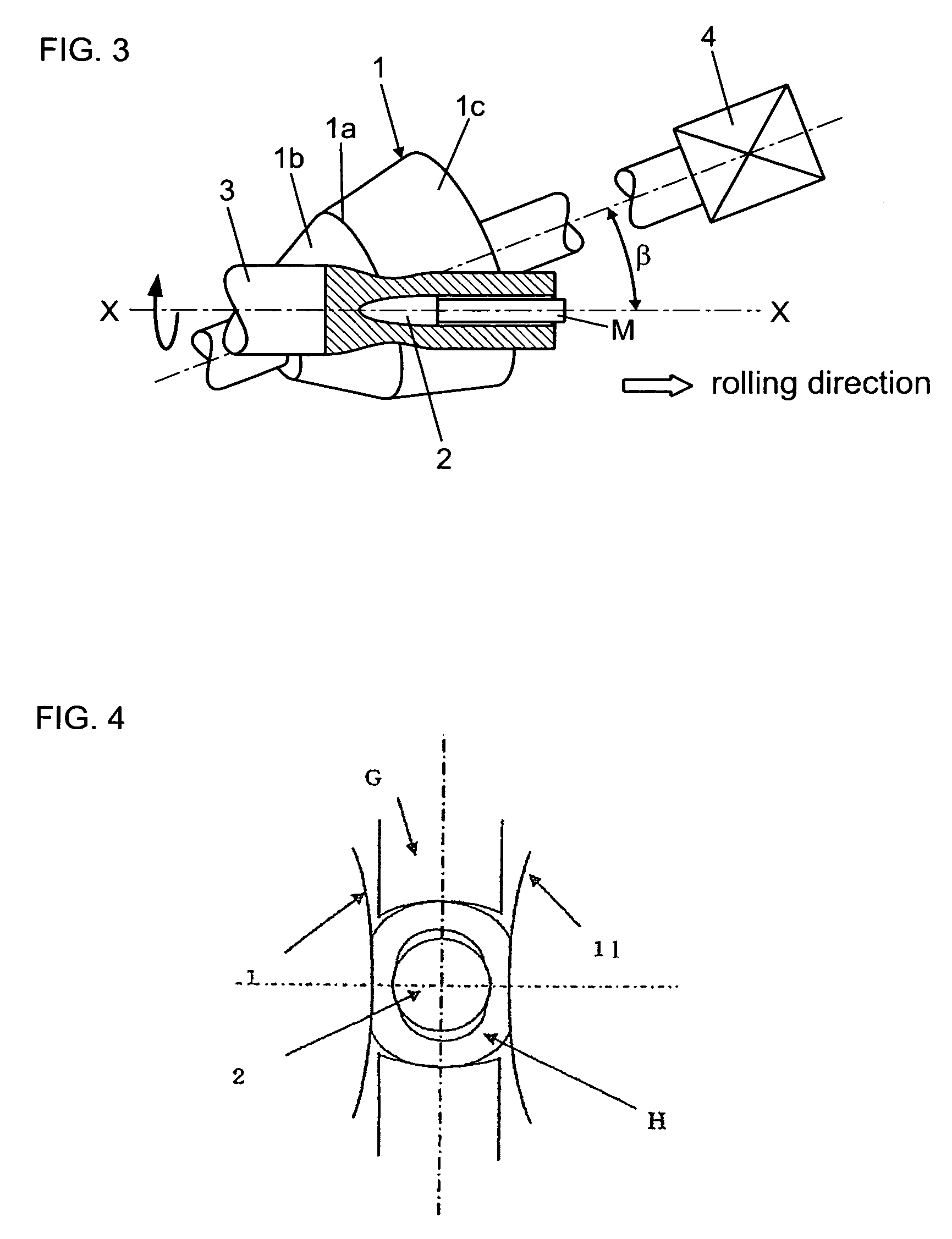
[0008]In the invention disclosed in Patent Document 2, the rotary forging effect in the midportion of a billet can be suppressed by using disk rolls in which the surface of each roll which contacts the material being rolled has a cross-sectional shape with a semicircular groove. In this case, however, if the rotational frequency of a billet is small or the rolling reduction of the outer diameter of a billet is small, slippage between the skew rolls and the billet increases in a piercer, and the rotary forging effect at the time of gripping of the billet by the rolls ends up increasing. In addition, the frictional resistance between a plug of the piercer and the billet increases, thereby increasing the shearing deformation and causing the occurrence of internal surface flaws. Moreover, oscillation of the billet increases in a transient (non-steady state) region as the billet is gripped by the skew rolls, and thickness deviations of the top portion of the resulting hollow shell worsen. Furthermore, in the invention disclosed by Patent Document 2, when the expansion ratio is large, the outer diameter of the bottom portion of the resulting hollow shell may increase under some conditions of the diameter of the disk rolls and the rotational frequency of the billet. An increase in the outer diameter of the bottom portion of a hollow shell causes, when the hollow shell is subsequently rolled through grooved rolls in a mill such as a mandrel mill, an increase in the load to be applied to the grooved rolls by over-filling of the material being rolled into roll gaps between groove flange portions and a decrease in the yield.
[0015]In a manufacturing process for a seamless tube according to the present invention, the frequency of rotary forging and shear deformation occurring in a transient region at the stage of billet gripping during piercing are suppressed. As a result, in the top portion of a hollow shell produced by piercing, the occurrence of internal surface flaws caused by the rotary forging effect and / or shear deformation can be prevented, and a worsening of thickness deviation can also be prevented, thereby preventing miss-rolling such as incomplete billet gripping or troubles in tube s bottom withdrawal. In addition, an increase in the outer diameter of the bottom portion of a hollow shell can be prevented, and a hollow shell having a high quality over its entire length from its top portion to its bottom portion can be reliably manufactured.
[0016]Thus, in accordance with the present invention, when a billet is pierced with a piercer to produce a hollow shell, the occurrence of rolling defects during piercing in the transient region of both the top portion and the bottom portion of the hollow shell can be reduced or eliminated, leading to a tremendous effect of increasing the yield and productivity of hollow shells. The effect of this invention of reducing or eliminating rolling defects in the transient rolling region of both the top portion and the bottom portion of a hollow shell could not possibly be achieved based on the inventions disclosed in either Patent Document 1 or Patent Document 2 which gives no consideration at all to improving rolling defects in the transient rolling regions of both the top portion and the bottom portion of a hollow shell.

Problems solved by technology

In this case, however, if the rotational frequency of a billet is small or the rolling reduction of the outer diameter of a billet is small, slippage between the skew rolls and the billet increases in a piercer, and the rotary forging effect at the time of gripping of the billet by the rolls ends up increasing.
In addition, the frictional resistance between a plug of the piercer and the billet increases, thereby increasing the shearing deformation and causing the occurrence of internal surface flaws.
Moreover, oscillation of the billet increases in a transient (non-steady state) region as the billet is gripped by the skew rolls, and thickness deviations of the top portion of the resulting hollow shell worsen.
An increase in the outer diameter of the bottom portion of a hollow shell causes, when the hollow shell is subsequently rolled through grooved rolls in a mill such as a mandrel mill, an increase in the load to be applied to the grooved rolls by over-filling of the material being rolled into roll gaps between groove flange portions and a decrease in the yield.
In the past, a hollow shell was made freed of internal surface flaws and thickness deviations over its entire length by cutting off its top portion or by repair of the top portion, but such a measure incontrovertibly increases the manufacturing costs.

Method used


Image

  • Process for manufacturing a seamless tube
  • Process for manufacturing a seamless tube
  • Process for manufacturing a seamless tube

Examples


example 1

[0078]The present invention will be explained more specifically with reference to examples.

[0079]A billet with an outer diameter of 70 mm was cut from the center of a billet of a continuously cast carbon steel containing 0.2% C having an outer diameter of 225 mm. The cut billet was heated to 1200° C. and subjected to piercing under the conditions shown in Table 2. The results of piercing are compiled in Table 3.

TABLE 2Dgφ 400mmDdφ 1100mmExp1.03-1.28θ13°d70mmDg / D11.06-1.28(Ns × Df)0.50.15-0.48

TABLE 3Increase inInternaltroubles inPercentbottomsurfaceIncompletebottomthicknessouterExpDg / D1(Np × Df)0.5flawsgrippingwithdrawaldeviationdiameter1.031.060.25◯◯◯◯◯This invention1.031.10.3◯◯◯◯◯This invention1.251.190.35◯◯◯◯◯This invention1.161.233◯◯◯◯◯This invention1.031.060.15NDXNDNDNDComparative1.251.230.2◯◯◯XXComparative1.121.280.25◯◯X◯NDComparative1.031.140.48X◯◯◯◯ComparativeND: not determinable

[0080]The mark “O” in Table 3 indicates that piercing could be performed without any problems, and...


PUM

PropertyMeasurementUnit
diameter Dgaaaaaaaaaa
outer diameteraaaaaaaaaa
diameter Ddaaaaaaaaaa

Abstract

A high quality hollow shell in which the occurrence of internal surface flaws caused by the rotary forging effect and / or shear deformation is prevented by suppressing the rotary forging frequency and shear deformation in a transient region at the stage of billet gripping and a worsening of thickness deviations in the top portion of the hollow shell is also prevented is reliably produced with preventing miss-rolling such as incomplete billet gripping and troubles in bottom withdrawal and an increase in the outer diameter of the hollow shell in the bottom portion. A billet is pierced while being rotated and advanced to produce a hollow shell, from which a seamless tube is finally manufactured, using a pair of skew rolls, a pair of disk rolls, and a plug under such conditions that each of the ratio (Dg / d) of the diameter Dg of the gorge portion of the skew rolls and the outer diameter d of the billet, the ratio (Dd / d) of the diameter Dd of the groove bottom of the disk rolls and the outer diameter d of the billet, the ratio (Dd / Dg) of the diameter Dg and the diameter Dd, the inlet face angle θ1 of the skew rolls, and the square root of the product (Ns×Df)0.5 of the rotational frequency Ns of the billet in a transient (non-steady state) region when billet gripping and the reduction ratio Df of the outer diameter of the billet satisfies a prescribed equation.

Description

TECHNICAL FIELD[0001]This invention relates to a process for manufacturing a seamless tube. Specifically, it relates to a process for manufacturing a seamless tube comprising piercing a billet in a piercer (a skew rolling mill) to produce a hollow shell.BACKGROUND ART[0002]Seamless tube is usually manufactured by the Mannesmann plug mill process or the Mannesmann mandrel mill process. In order to manufacture seamless tube by such a process, first, a solid rod-shaped billet (referred to in this description simply as a billet) is introduced into a heating furnace and heated therein to a predetermined temperature. The billet is then removed from the heating furnace and is rolled for piercing in a piercer to produce a hollow shell. The hollow shell is then rolled for elongation using a plug mill or a mandrel mill or a similar rolling mill in which primarily the wall thickness of the hollow shell is reduced. Thereafter, it is rolled for sizing using a reducing mill such as a sizer or a s...

Claims


Application Information

Patent Timeline
Patent Type & Authority Applications(United States)
IPC IPC(8): B21B19/06
CPCB21B19/04B21B27/024B21B27/025B21B2275/06B21B2267/02B21B2267/06B21B2275/04B21B2261/08
Inventor YAMAKAWA, TOMIOSHIMODA, KAZUHIRO
Owner NIPPON STEEL CORP
Why Eureka
Try Eureka