
Connection System for a Respiratory Humidifier

a technology of connecting system and humidifier, which is applied in the direction of connection contact material, connection device connection, respirator, etc., can solve the problems of limiting the scope of design possibilities of respiratory humidifier, affecting the appearance and practicality of respiratory humidifier, and logical improvements in this regard are almost impossible to make with existing devices, so as to achieve the effect of reducing operating errors and flexibly being used

Active Publication Date: 2014-09-04
HAMILTON MEDICAL AG
View PDF4 Cites 25 Cited by
  • Summary
  • Abstract
  • Description
  • Claims
  • Application Information

AI Technical Summary

Benefits of technology

The invention provides a connecting system for a ventilation tube and a respiratory humidifier. The system includes a first connection element on the liquid container, a second electrical contact element on the housing, and two second connection elements that can be connected to the ventilation tube and the electrical line, respectively. The first connection element can be connected to the second connection element in two directions, allowing for a more flexible and compact design of the respiratory humidifier. The system also allows for the connection of the inhalation tubes after the liquid container is connected, further reducing the risk of operating errors and malfunctions. Overall, the invention offers a more efficient and reliable connection system for ventilation and humidification in respiratory therapy.

Problems solved by technology

The disadvantage of the tube connecting system described in EP 1 369 141 A1 is that it can be placed onto the respiratory humidifier in only one direction, namely, from above.
Before the connection is made, the electrical contact elements on the housing project awkwardly from the housing as independent elements and thus interfere with the appearance and practicality of the respiratory humidifier.
Another disadvantage arising from this connecting system is that it limits the scope of possibilities for designing the respiratory humidifier.
Logical improvements in this regard are therefore almost impossible to make with the existing devices.

Method used


Image

  • Connection System for a Respiratory Humidifier
  • Connection System for a Respiratory Humidifier
  • Connection System for a Respiratory Humidifier

Examples


Embodiment Construction

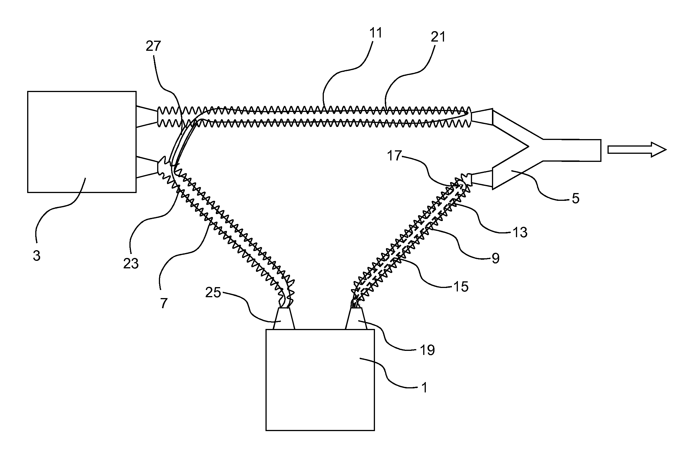
[0026]FIG. 1 shows a schematic view of a preferred embodiment of a ventilation system having a connecting system according to the invention. A respiratory humidifier 1 is arranged between a respirator 3 and a Y-piece 5 and connected to them by a first inhalation or inspiration tube 7 and a second inhalation or inspiration tube 9. The simply designed end of the Y-piece 5 is pointing toward the patient to be ventilated, as indicated by the arrow. Finally, an exhalation or expiration tube 11 is arranged between the respirator 3 and the remaining end of the Y-piece 5.

[0027]A flow of dry breathing gas is produced by a blower (not shown), for example, in the respirator 3; this gas leaves the ventilator through the first inhalation tube 7 and proceeds toward the respiratory humidifier 1. There the breathing gas is conducted in the known manner into a liquid container (not shown in FIG. 1), where it is heated and humidified by the heated liquid. The heated and humidified breathing gas leave...


PUM


Abstract

A connecting system for connecting a ventilation tube to a respiratory humidifier (1) is provided, wherein the ventilation tube comprises an electrical line and the respiratory humidifier (1) comprises a housing (2) and a liquid container (4), the connection system including a first connection element (6) arranged on the liquid container (4); a first electrical contact element (24) arranged on the housing (2); and a second connection element (14), which can be connected to the ventilation tube (7, 9) and comprises a second electrical contact element (16), which can be connected to the electrical line of the ventilation tube (7, 9); wherein the first connection element (6) and the second connection element (14) can be connected to each other in a first connecting direction in such a way that, by establishment of the pneumatic connection of the ventilation tube (7, 9) to the liquid container (4), the electrical connection of the first contact element (24) to the second contact element (16) is produced. The electrical connection of the first contact element (24) to the second contact element (16) can be established in a second connecting direction different from the first connecting direction, preferably in a direction essentially perpendicular to the first connecting direction.

Description

FIELD OF INVENTION[0001]The present invention relates to a connecting system for connecting ventilation tubes to a respiratory humidifier for the ventilation of patients with breathing gas and to a ventilation system comprising a ventilator, a respiratory humidifier with the connecting system, and a corresponding system of ventilation tubing.[0002]When patients are being mechanically ventilated on an intensive-care ward, for example, the patient to be ventilated is connected pneumatically to the ventilator or respirator by a system of ventilation tubing. Because the breathing gas supplied to the patient must be adjusted with respect to temperature and humidity to meet the physiological needs of the patient, a respiratory humidifier is arranged in the inhalation or inspiration tube to heat and humidify the breathing gas. The respiratory humidifier comprises a liquid container filled with distilled water, through which the breathing air is conducted and humidified.[0003]To prevent moi...

Claims


Application Information

Patent Timeline
Patent Type & Authority Applications(United States)
IPC IPC(8): A61M16/00A61M16/08A61M16/16H01R13/00
CPCA61M16/0003H01R13/005A61M16/0816A61M2016/0036A61M16/16A61M16/0057A61M16/0875A61M16/0833A61M16/022A61M16/1075A61M16/1095A61M2205/14A61M2205/3368A61M2205/3653
Inventor BUECHI, RUDOLFFREI, RETOMAEDER, MARCGRANZOTTO, THOMASZOLKOS, AXEL
Owner HAMILTON MEDICAL AG
Learn More