Dynamic Augmented Reality Vision Systems

a vision system and dynamic technology, applied in closed circuit television systems, instruments, computing, etc., can solve the problems of inability to use and invent the art, and achieve the effects of increasing the level of detail, low level of augmentation, and increasing imagery

Inactive Publication Date: 2014-09-04
GEOVECTOR
View PDF6 Cites 24 Cited by
  • Summary
  • Abstract
  • Description
  • Claims
  • Application Information

AI Technical Summary

Benefits of technology

[0013]Either by measurement and sensors, among other means, imaging systems presented herein determine atmospheric, environmental and spatial particulars and conditions. Where these conditions warrant an increase in the level of detail—same is provided by the computer graphics generation facility. Thus an augmented reality imaging system may provide a low level of augmentation on a clear day. However, when a fog bank tends to obscure a view, the imager can respond to that detected condition and provide increased imagery to improve the portions of the optically captured image which are obscured by fog. Thus, an augmented reality system may be responsive to environmental conditions and states in that they are operable to adjust the level of augmentation to account for specific detected conditions.
[0014]These augmented reality imaging systems are not only responsive to environmental conditions but are also responsive to user choices with respect to declared objects of interest or points of interest. Where a user indicates a preferential interested by selecting a specific object, the augmentation provided by a computer graphics generation facility may favor the selected object to the detriment of other objects less preferred. In this way, an augmented reality imaging system of this teaching can permit a user to “see through” solid objects which otherwise tend to interrupt a view of some highly important objects of great interest.

Problems solved by technology

While systems and inventions of the art are designed to achieve particular goals and objectives, some of those being no less than remarkable, these inventions of the art have nevertheless include limitations which prevent uses in new ways now possible.
Inventions of the art are not used and cannot be used to realize advantages and objectives of the teachings presented herefollowing.

Method used


Image

  • Dynamic Augmented Reality Vision Systems
  • Dynamic Augmented Reality Vision Systems
  • Dynamic Augmented Reality Vision Systems

Examples


Embodiment Construction

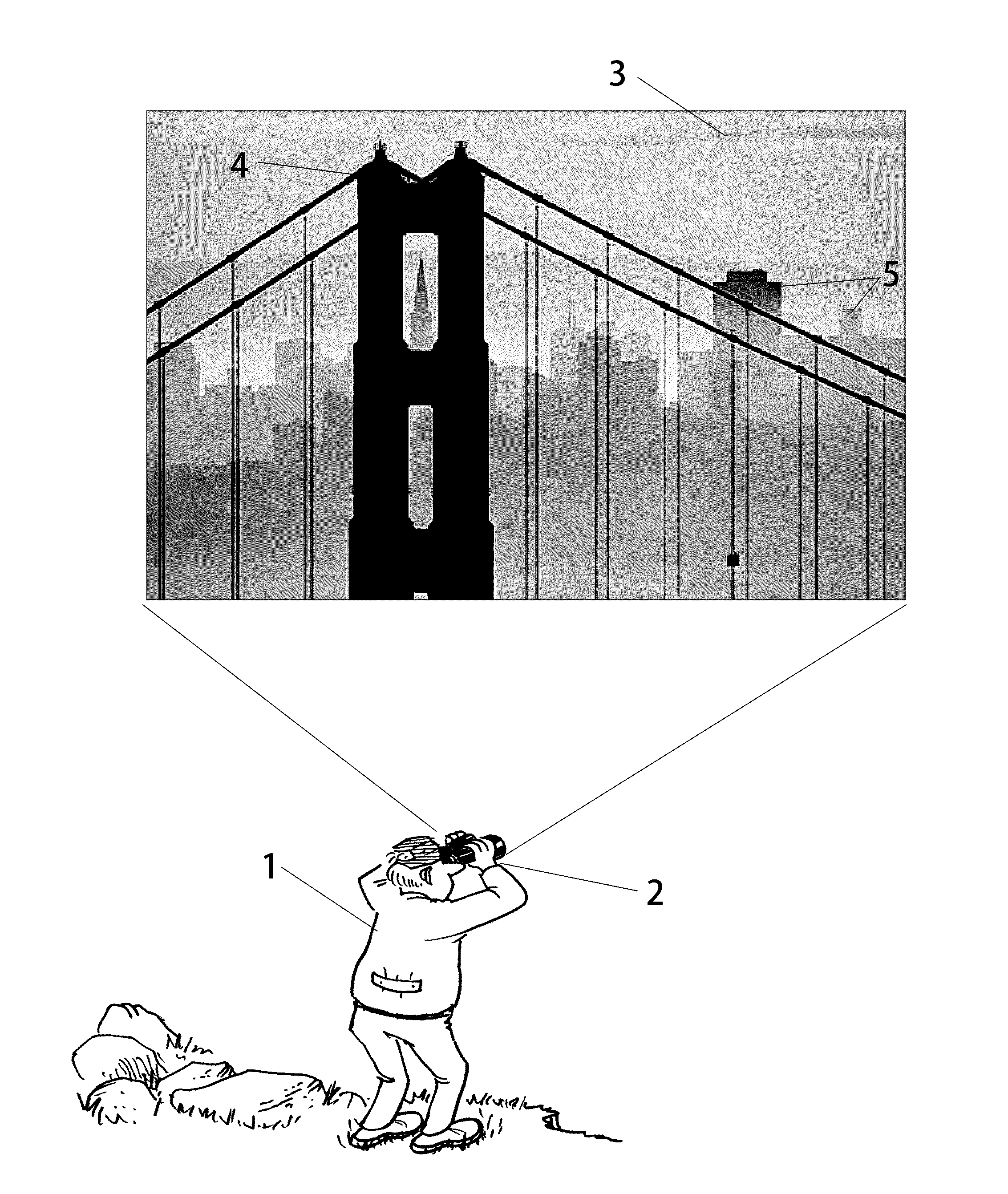
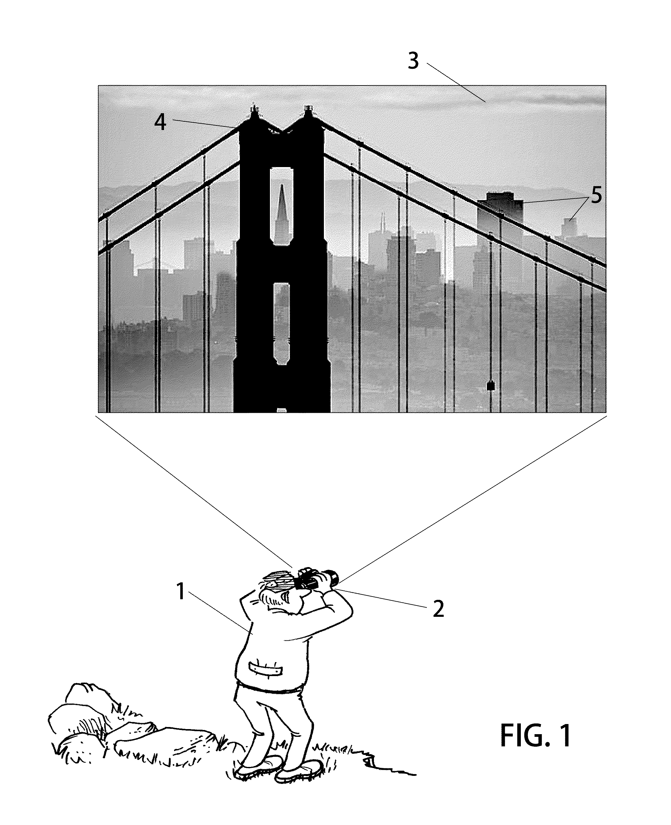
[0028]In advanced electronic vision systems, optical images are formed by a lens when light falls incident upon an electronic sensor to form a digital representation of a scene being addressed. Presently, sophisticated cameras use image processing techniques to draw conclusions about the states of a physical scene being imaged, and states of the camera. These states include the physical nature of objects being imaged as well as those which relate to environments in which the objects are found. While it is generally impossible to manipulate the scene being imaged in response to analysis outputs, it is relatively easy to adjust camera subsystems accordingly.

[0029]In one illustrative example, a modern digital camera need only analyze an image signal superficially to determine an improper white balance setting due to artificial lighting. In response to detection of this condition, the camera can adjust the sensor white balance response to improve resulting images. Of course, an ‘auto wh...


PUM


Abstract

Imaging systems which include an augmented reality feature are provided with automated means to throttle or excite the augmented reality generator. Compound images are presented whereby an optically captured image is over late with a pewter generated image portion to form the complete augmented image for presentation to a user. Upon the particular conditions of the imager, imaged scene and the Imaging environment, these imaging systems include automated responses. Computer-generated images which are overlaid optically captured images are either bolstered all in the detail and content where an increase in information is needed, or they are tempered where a decrease in information is preferred as determined by prescribed conditions and values.

Description

BACKGROUND OF THE INVENTION[0001]1. Field[0002]The following invention disclosure is generally concerned with electronic vision systems and specifically concerned with highly dynamic and adaptive augmented reality vision systems.[0003]2. Related Systems[0004]Vision systems today include video cameras having LED displays, electronic documents, infrared viewers among others. Various types of these electronic vision systems have evolved to include computer-based enhancements. Indeed, it is now becoming possible to use a computer to reliably augment optically captured images with computer-generated graphics to form compound images. Systems known as Augmented Reality capture images of scenes being addressed with traditional lenses and sensors to form an image to which computer-generated graphics may be added.[0005]In some versions, simple real-time image processing yields a device with means for superimposing graphics generated by a computer with optically captured images. For example, e...

Claims


Application Information

Patent Timeline
Patent Type & Authority Applications(United States)
IPC IPC(8): H04N7/18
CPCH04N7/18G06T19/006G06T2210/36
Inventor ELLENBY, PETER
Owner GEOVECTOR
Why Eureka
Try Eureka