Time-optimal trajectories for robotic transfer devices

a technology of robotic transfer device and time-optimal trajectory, which is applied in the direction of program control, instrumentation, total factory control, etc., can solve the problems of increasing peak torque requirements, affecting performance, size, cost and life, and conventional trajectory generation methods generally do not account for torque constraints or do not, and the viability of this approach can be limited by the world application

Active Publication Date: 2014-09-04
BOOKS AUTOMATION US LLC
View PDF7 Cites 21 Cited by
  • Summary
  • Abstract
  • Description
  • Claims
  • Application Information

AI Technical Summary

Problems solved by technology

While robotic systems for carrying light payloads can be over-designed to provide necessary torque margins, increased peak torque requirements become a factor for performance, size, cost and life of both direct-drive and harmonic-drive robotic manipulators for high or heavy payloads.
Conventional trajectory generation methods generally do not account for torque constraints or do not produce a smooth commanded trajectory.
While time-optimal, some real world applications can limit the viability of this approach due to the presence of variable or unquantifiable system resonances.
More particularly, abrupt changes in jerk (change in acceleration with respect to time) can serve as a broad spectrum excitation of the system, resulting in unacceptably long settle times at the final position.
Conventional systems to remove discontinuities in trajectories from bang-bang control, such as Bobrow et al., by constraining trajectory profiles or kinematic characteristics of the trajectory profiles such as acceleration, jerk and jerk rate result in non-optimal trajectories and hence lower efficiencies.

Method used


Image

  • Time-optimal trajectories for robotic transfer devices
  • Time-optimal trajectories for robotic transfer devices
  • Time-optimal trajectories for robotic transfer devices

Examples


Embodiment Construction

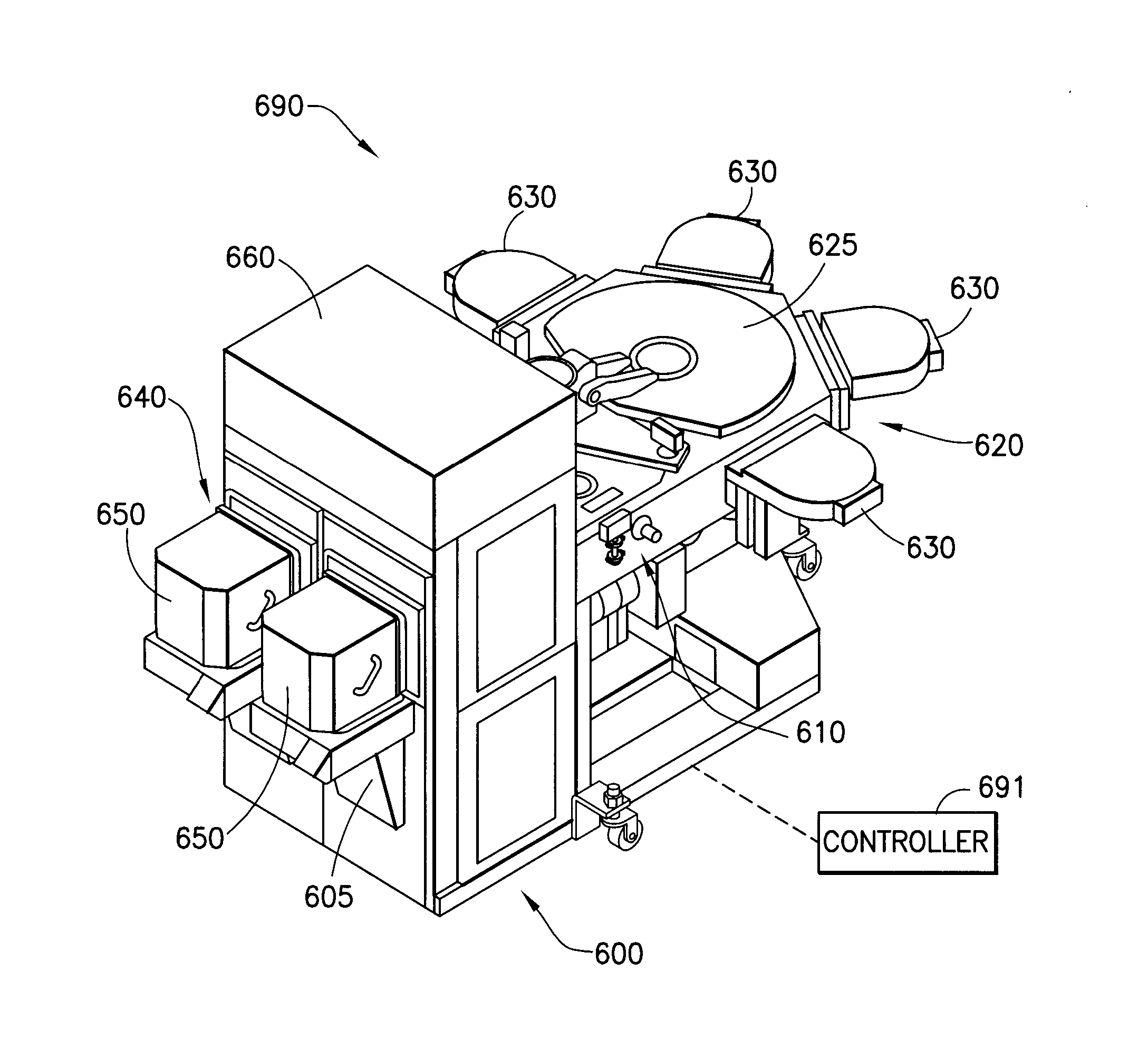
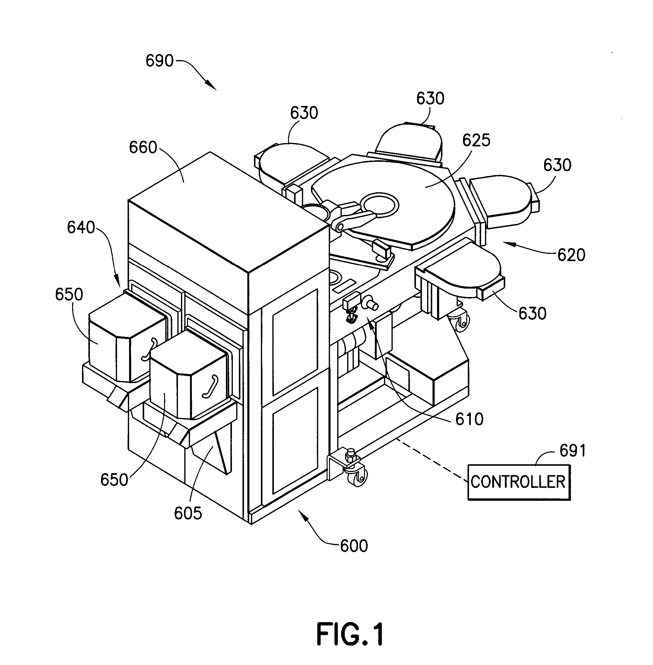
[0021]FIG. 1 illustrates an exemplary substrate processing apparatus in which aspects of the disclosed embodiment can be used. Although the aspects of the disclosed embodiment will be described with reference to the drawings, it should be understood that the disclosed embodiment can be embodied in many alternate forms. In addition, any suitable size, shape or type of elements or materials could be used.

[0022]As can be seen in FIG. 1, a substrate processing apparatus, such as for example a semiconductor tool station 690 is shown in accordance with an aspect of the disclosed embodiment. Although a semiconductor or substrate processing tool is shown in the drawings, the aspects of the disclosed embodiment described herein can be applied to any tool station or application employing robotic manipulators. The substrate processing tool 690 may include different sections having, for example, different atmospheres separated by, for example, a load lock 610 (e.g. inert gas on one side and vac...


PUM


Abstract

A time-optimal trajectory generation method, for a robotic manipulator having a transport path with at least one path segment, comprising generating a forward time-optimal trajectory of the manipulator along the at least one path segment from a start point of the at least one path segment towards an end point of the at least one path segment, generating a reverse time-optimal trajectory of the manipulator along the at least one path segment from the end point towards the start point of the at least one path segment, and combining the time-optimal forward and reverse trajectories to obtain a complete time-optimal trajectory, where the forward and reverse trajectories of the at least one path segment are blended together with a smoothing bridge joining the time-optimal forward and reverse trajectories in a position-velocity reference frame with substantially no discontinuity between the time-optimal forward and reverse trajectories.

Description

CROSS-REFERENCE TO RELATED APPLICATIONS[0001]This application is the National Stage of International Application No. PCT / US2012 / 052977 having International Filing date, 30 Aug. 2012, which designated the United States of America, and which International Application was published under PCT Article 21 (s) as WO Publication 2013 / 033289 A1 and which claims priority from, and benefit of U.S. Provisional Application No. 61 / 530,651 filed on 2 Sep. 2011, the disclosures of which are incorporated herein by reference in their entireties.BACKGROUND[0002]1. Field[0003]The exemplary embodiments generally relate to robotic manipulators and, more particularly, to a method and means for the generation of smooth time-optimal trajectories for robotic manipulators.[0004]2. Brief Description of Related Developments[0005]Trajectory generation is typically used when transferring substrates held by a robotic manipulator from one place to another. While robotic systems for carrying light payloads can be ov...

Claims


Application Information

Patent Timeline
Patent Type & Authority Applications(United States)
IPC IPC(8): B25J9/16
CPCG05B2219/40466B25J9/1664H01L21/67259H01L21/67742H01L21/67766G05B19/416G05B2219/40449Y02P90/02
Inventor KRISHNASAMY, JAYARAMANHOSEK, MARTIN
Owner BOOKS AUTOMATION US LLC
Why Eureka
Try Eureka