Shower door assembly

Inactive Publication Date: 2014-09-11
FOSHAN IDEAL
7 Cites 5 Cited by

AI-Extracted Technical Summary

Problems solved by technology

This procedure is very inconvenient and time-consuming.
Furthermore, the drilling operation may cause dam...

Method used

[0035]To facilitate the deformation, the tubular end 42′ can be made of elastic materials. To further facilitate the deformation, as shown in FIG. 6, the tubular end has a plurality of linear openings 44′ parallel to each other.
[0036]The shower door assembly in the above examples can further comprise a top frame and a bottom frame, and the eccentric block can be received in the top frame and a bottom frame. The...

Benefits of technology

[0014]By using the present invention, when the shower door is assembled, there is no need for drilling or any other particular tools. The shower door can be assem...

Abstract

A shower door assembly is provided comprising a stationary frame, a movable frame having at least one through hole, and at least one adjusting assembly, wherein each of the at least one adjusting assembly comprises a fixing block located between the stationary frame and the movable frame, and receivable in the stationary frame, the fixing block having a channel, a deformable element receivable in the channel of the fixing block, and a fastening element passing through the through hole of the movable frame to connect with the deformable element.

Application Domain

Technology Topic

Image

  • Shower door assembly
  • Shower door assembly
  • Shower door assembly

Examples

  • Experimental program(1)

Example

[0022]Elements that are irrelevant to the spirit of the present invention are omitted for clarity.
DETAILED DESCRIPTION OF THE INVENTION
[0023]The terminology used herein is for the purpose of describing particular embodiments only and is not intended to be limiting of example embodiments of the invention. As used herein, the singular forms “a,”“an,” and “the,” are intended to include the plural forms as well, unless the context clearly indicates otherwise. As used herein, the terms “and/or” include any and all combinations of one or more of the associated listed items. It will be further understood that the terms “comprises”“comprising”“includes” and/or “including” when used herein, specify the presence of stated features, integers, steps, operations, elements, and/or components, but do not preclude the presence or addition of one or more other features, integers, steps, operations, elements, components, and/or groups thereof.
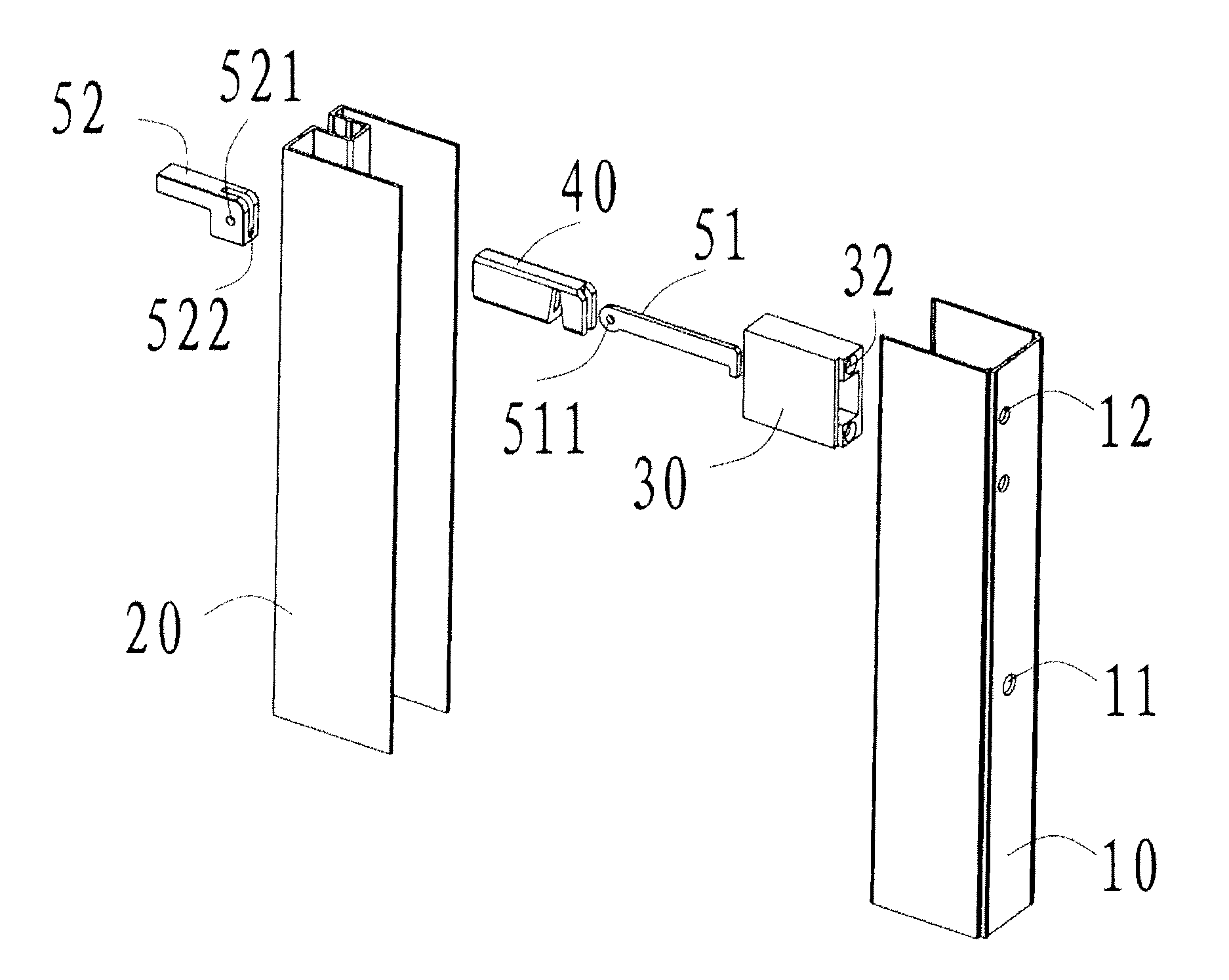
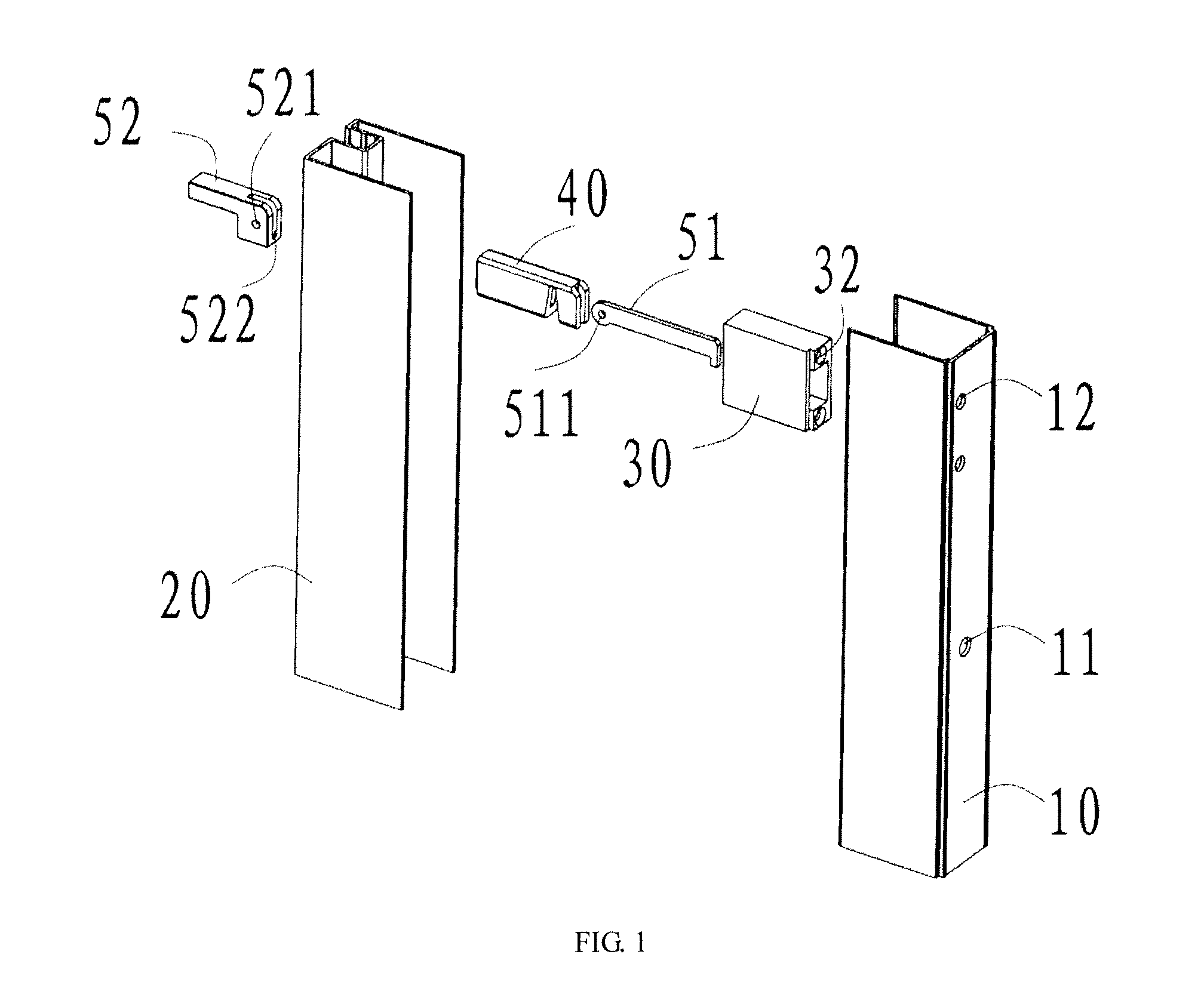
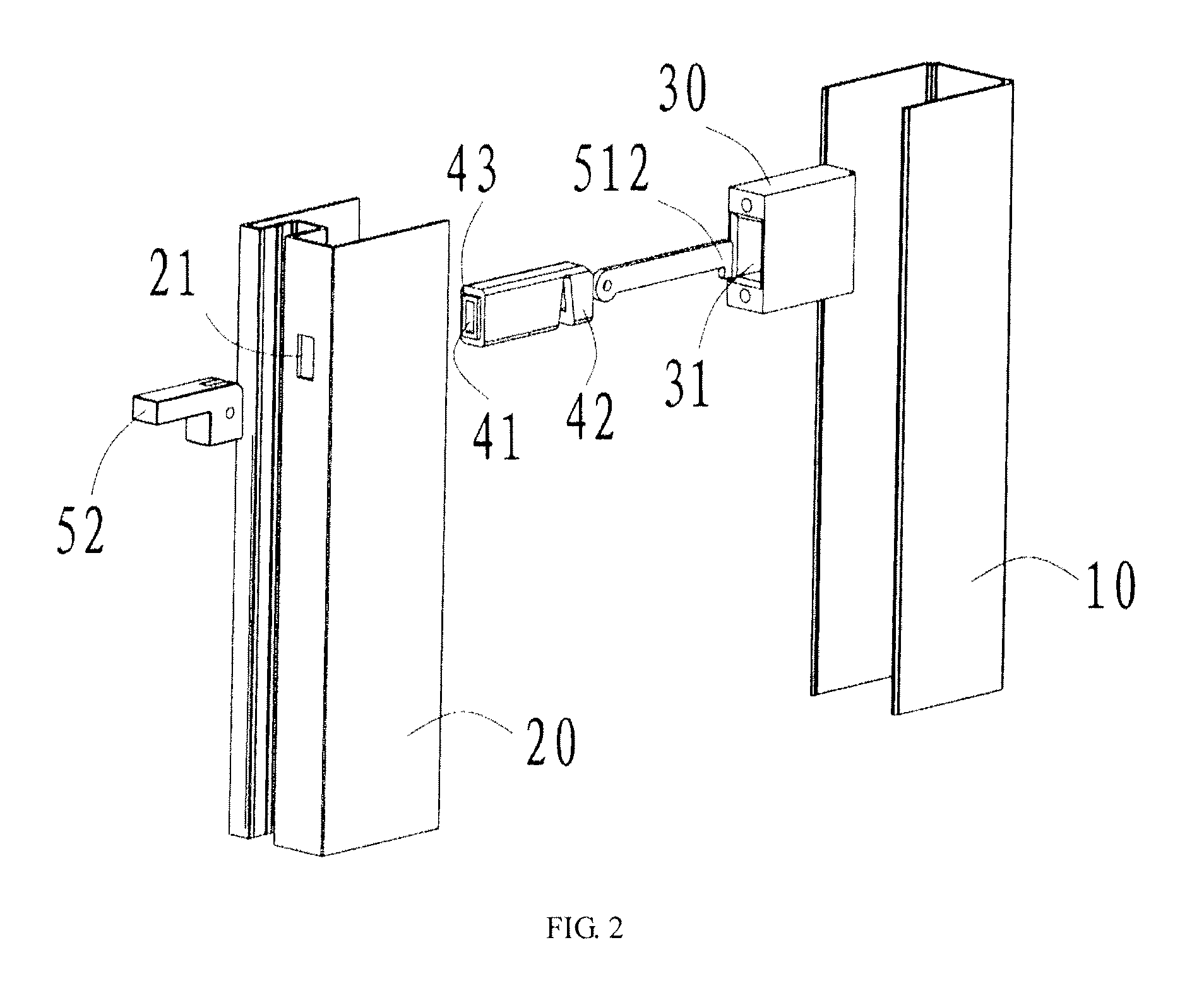
[0024]With reference to FIGS. 1 and 2 which show main parts of an exemplified shower door assembly, the shower door assembly comprises a stationary frame 10 and a movable frame 20 having a through hole 21. The stationary frame 10 has a U shape and a slot for mounting of glass. The shower door assembly further comprises an adjusting assembly which mainly comprises a fixing block 30, a deformable element 40 and a fastening element, the fastening element passing through the through hole 21 to connect with the deformable element 40.
[0025]The stationary frame 10 is used to secure to a wall surface. The stationary frame 10 can be attached to a wall through many ways. The stationary frame 10 in FIG. 1 comprises a screw hole 11, such that fasteners (such as a crew) can pass through it to fix the stationary frame 10 to the wall. Of course, the person skilled in the art knows other methods applicable to achieve said secure, for example, by adhesives.
[0026]The fixing block 30 is partially received within the stationary frame 10. As shown in FIG. 1, the fixing block 30 comprises a through hole 32, and the stationary frame 10 comprises a screw hole 12. A fastener can pass through the through hole 32 and the screw hole 12 to connect the fixing block 30 with the stationary frame 10. The size of the fixing block 30 should be smaller than the inner space of the stationary frame 10, assuring the fixing block receivable within the stationary frame.
[0027]The fixing block 30 has a channel 31, and the deformable element 40 is receivable in the channel 31. As shown in FIG. 2, the channel 31 is a cuboid channel, the deformable element 40 has a first hook end 42, and the cross-section of the first hook end 42 has the same size as the cross-section of the channel 31. One end of the deformable element 40 that is contacting with the movable frame has a front edge 43, making the end of the deformable element engagable with one side of the movable frame.
[0028]The fastening element 50 comprises a pulling rod 51 and an eccentric block 52 respectively located at one side of the movable frame and rotatably connected with each other through a shaft. A slot 41 is disposed within the deformable element 40 and the pulling rod 51 is receivable in the slot 41. The pulling rod 51 has a second hook end 512, and the second hook end 512 engages with the first hook end 42 at an outer side of the first hook end 42.
[0029]The pulling rod 51 and an eccentric block 52 can be rotatably connected with each other in many ways. As shown in FIG. 1, the eccentric block 52 has a pin hole 521 and a groove 522, one end of the pulling rod 51 comprises a hole 511. The pulling rod passes through the slot 41 and inserts into the groove 522, such that the pulling rod 51 and an eccentric block 52 can be connected by a fastener (such as a pin) passing through the pin hole 521 and the hole 511.
[0030]With reference to FIG. 3 which shows an assembled view of the shower door assembly in FIG. 1, the fixing block 30 is fixed in the stationary frame, the pulling rod (not shown) passes through the slot of the deformable element and the through hole of the movable frame to connect with the eccentric block 52. The deformable element 40 is fixed in the movable frame by the engagement of the first hook end and the second hook end. When the movable frame moves towards the stationary frame, the deformable element 40 would insert into the channel of the fixing block 30.
[0031]With reference to FIG. 4 which shows a working view of the shower door assembly in FIG. 1, (a) refers to an opening position and (b) refers to a fastening position. The eccentric block 52 has an L shape with two arms, one arm as a handle and the other arm as a supporter when rotated. At the opening position (a), the eccentric block 52 connects with the movable frame (in dashed lines) at its opening surface, and at the fastening position (b), the eccentric block 52 connects with the movable frame at its fastening surface.
[0032]Because the distance between the shaft and the opening surface is smaller than the distance between the shaft and the fastening surface, when rotating the eccentric block, the pulling rod 51 would be pulled and move towards the movable frame, which makes the first hook end 42 be pulled by the second hook end 512 and move towards the movable frame. As one end of the deformable element 40 is engaging with the movable frame, the first hook end 42 would be deformed. Since the first hook end 42 has a cross-section of the same size as a cross-section of the channel, the deformed first hook end 42 would compress the inner surface of the channel so as to fix the deformable block inside the channel, such that the movable frame would be fixed to the stationary frame.
[0033]FIG. 5 shows an exploded view of another exemplified shower door assembly, and FIG. 6 shows an enlarged view of a portion of the shower door assembly in FIG. 5. The shower door assembly shown in FIG. 5 is basically the same as the shower door assembly shown in FIG. 1, except that the channel 31′ of the fixing block has a cylinder shape, and the deformable element has a tubular end 42′, the pulling rod has a columnar end 512′, the outer diameter of the columnar end 512′ is larger than the inner diameter of the tubular end 42′. The tubular end 42′ has a cross-section of the same size as a cross-section of the channel 31′ of the fixing block
[0034]Similarly to FIG. 4, when rotating the eccentric block, the pulling rod 51′ would be pulled and move towards the movable frame. As the deformable element 40′ has a front edge 43′ engagable with the movable frame, the columnar end 512′ of the pulling rod 51′ would insert into the tubular end 42′ of the deformable element 40′ to deform the tubular end 42′. Since the tubular end 42′ has a cross-section of the same size as the cross-section of the channel of the fixing block, the deformed tubular end 42′ would compress the inner surface of the channel so as to fix the deformable block inside the channel, such that the movable frame would be fixed to the stationary frame.
[0035]To facilitate the deformation, the tubular end 42′ can be made of elastic materials. To further facilitate the deformation, as shown in FIG. 6, the tubular end has a plurality of linear openings 44′ parallel to each other.
[0036]The shower door assembly in the above examples can further comprise a top frame and a bottom frame, and the eccentric block can be received in the top frame and a bottom frame. The top frame and the bottom frame are respectively disposed on two ends of the movable frame and perpendicular to the movable frame. The top and bottom frames can be detachably connected with the movable frame in appropriate ways. A glass door can be arranged between the top and bottom frames. The top and bottom frame can guide the sliding of the glass door, protect the eccentric block and enhance its appearance.
[0037]It should be understood that various example embodiments have been described with reference to the accompanying drawings in which only some example embodiments are shown. Specific structural and functional details disclosed herein are merely representative for purposes of describing example embodiments. The present invention, however, may be embodied in many alternate forms and should not be construed as limited to only the example embodiments set forth herein.

PUM

no PUM

Description & Claims & Application Information

We can also present the details of the Description, Claims and Application information to help users get a comprehensive understanding of the technical details of the patent, such as background art, summary of invention, brief description of drawings, description of embodiments, and other original content. On the other hand, users can also determine the specific scope of protection of the technology through the list of claims; as well as understand the changes in the life cycle of the technology with the presentation of the patent timeline. Login to view more.

Similar technology patents

6-oxo-pipecolic acid quantitation by mass spectrometry

PendingUS20220057371A1Less time-consumingComponent separationMass spectrometric analysisMolecular biologyAldehyde formation
Owner:UNIV OF COLORADO THE REGENTS OF

Classification and recommendation of technical efficacy words

  • Convenient to assemble
  • Less time-consuming

Express card adapter card

InactiveUS7059913B1Convenient to assembleConvenient and economical to manufactureCoupling device connectionsElectric discharge tubesEngineeringFront and back ends
Owner:D&C TECH

Wheel assembly

InactiveUS20070119661A1Simplify structureConvenient to assembleBraking element arrangementsSledge wheelsEngineeringMechanical engineering
Owner:CHANG CHIN LIN

Transmission module assembly having printed circuit board

ActiveUS6926540B1Reduce assembly processConvenient to assembleCouplings bases/casesFixed connectionsPrinted circuit boardElectrical connector
Owner:HON HAI PRECISION IND CO LTD

Ceiling loudspeaker

InactiveUS6870943B2Convenient to assembleStale in connectionMicrophonesLoudspeakersLoudspeakerEngineering
Owner:LIU HUNG MING

Headgear equipped with laser hair care apparatus

InactiveUS20100242155A1High degree of attentionLess time-consumingLight therapyHatsBiomedical engineeringHands free
Owner:CARULLO JR JOHN F

Articles and methods for applying color on surfaces

InactiveUS20060165979A1Permanent effectLess time-consumingCovering/liningsDecorative surface effectsEngineeringAdhesive
Owner:KINSEY VON ADONIRAM +5

Power control in mobile radio communications systems

InactiveUS20050143112A1Reduce complexityLess time-consumingPicture reproducers using cathode ray tubesPicture reproducers with optical-mechanical scanningEngineeringTransmitted power
Owner:OPTIS WIRELESS TECH LLC
Why Eureka
Try Eureka