Shower door assembly

a technology for shower doors and parts, applied in the direction of fastening means, rod connections, mechanical devices, etc., can solve the problems of shower doors being damaged, and the installation process is very inconvenient for operators and time-consuming, and achieves convenient and quick installation, simple structure, and satisfying the appearance and quality of products

Active Publication Date: 2014-09-11
FOSHAN IDEAL
View PDF7 Cites 43 Cited by
  • Summary
  • Abstract
  • Description
  • Claims
  • Application Information

AI Technical Summary

Benefits of technology

[0011]The shower door assembly according to the present invention has simple structures and is convenient and quick to install without drilling holes in the installation process. Meanwhile, the present invention can assure a satisfying appearance and quality of the products because there is no need to drill holes on the surface of the frames made of, for example, aluminum.

Problems solved by technology

However, the installation process is very inconvenient to operators and time-consuming.
Moreover, the drilling may cause damages or scares to surfaces of the frames made of, for example, aluminum or its alloys, and in extreme cases, the drilling may cause the shower doors destroyed.

Method used


Image

  • Shower door assembly
  • Shower door assembly
  • Shower door assembly

Examples


example 1

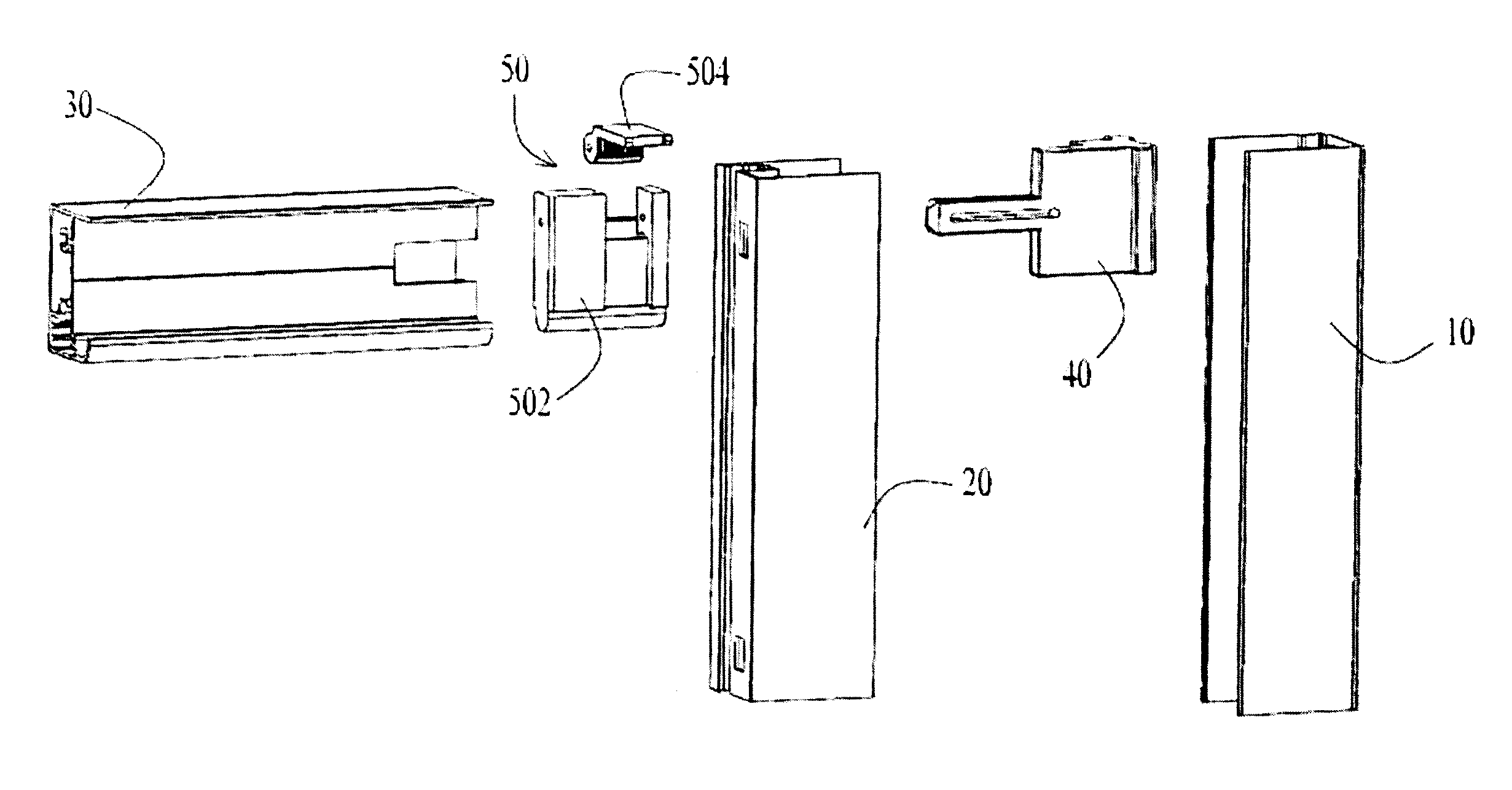
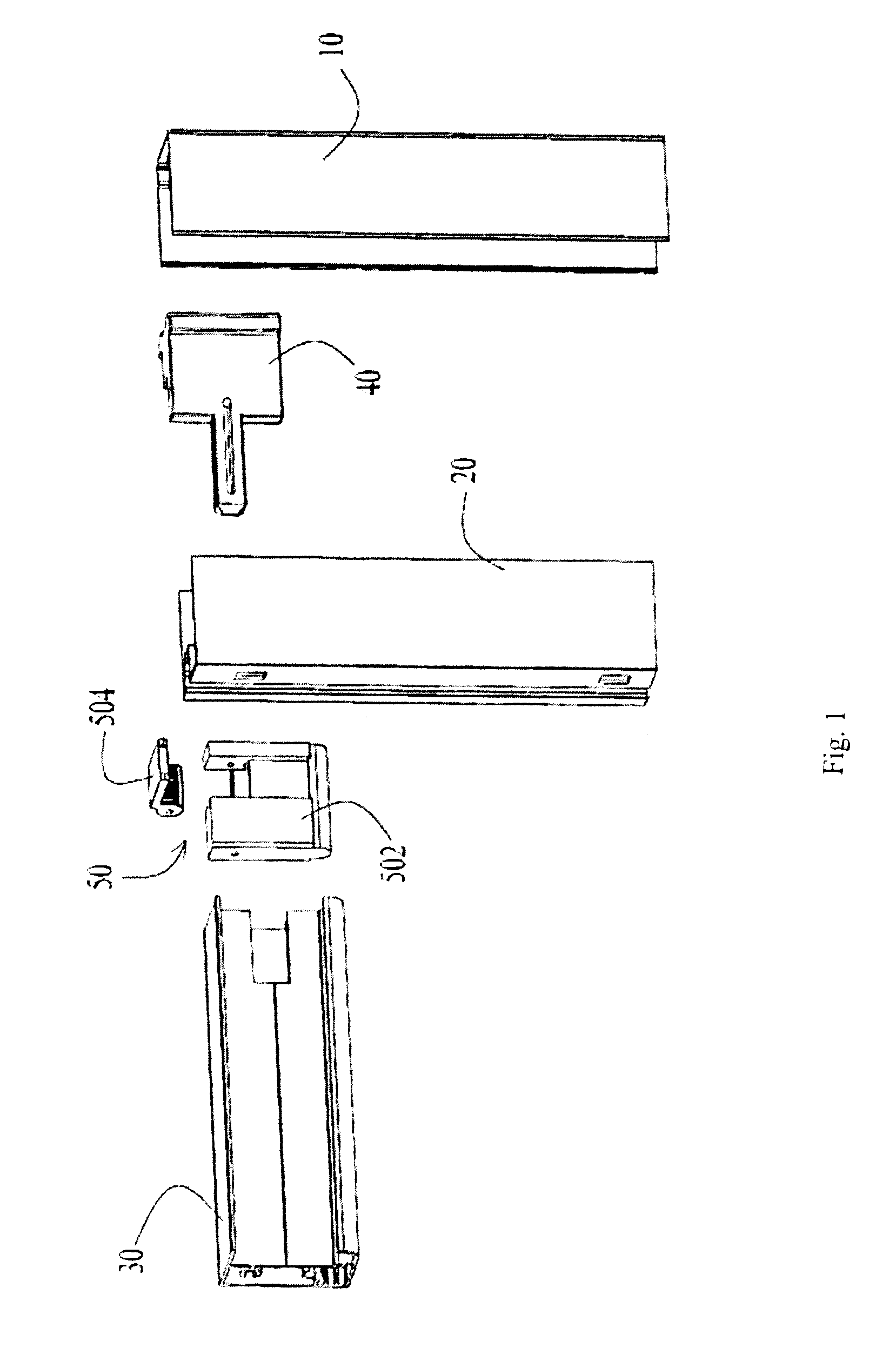
[0028]Referring to FIG. 1, an exemplary shower door assembly primarily comprises a stationary frame 10, a movable frame 20, an upper frame 30, a glass door (not shown) and an adjusting assembly. The assembly primarily includes an adjusting block 40 and a fixing block 50 having a base portion 502 and an eccentric rotary block 504.

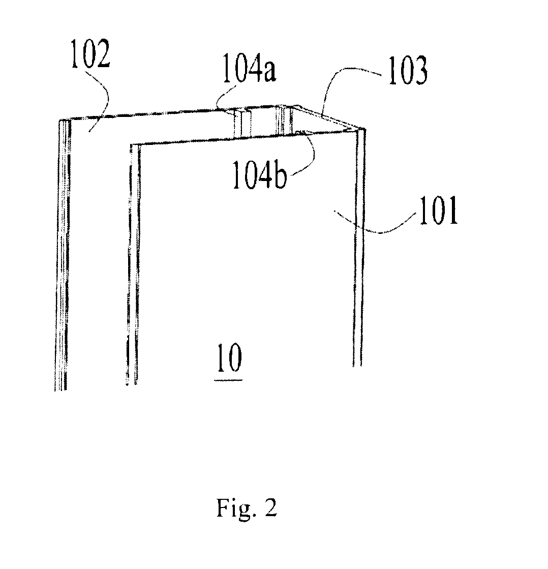
[0029]Specifically, referring to FIG. 2, the stationary frame 10 includes two transverse plates and a lateral plate 103 which form a space together for receiving the adjusting block 40. Baffles 104a, 104b which are opposite to one another extend respectively from the two transverse plates toward the space to form a guiding groove with the lateral plate 103 together. The stationary frame 10 can be fixing to a wall in a suitable manner. In this example, the stationary frame 10 is fixed to the wall by a fastener through a screw hole (not shown) disposed in the stationary frame 10. It is possible to fix the stationary frame to the wall in other manners, for exam...

example 2

[0038]The shower door assembly described in example 1 is substantially similar to the shower door assembly described in example 2 except the connection of the adjusting block 40 with the stationary frame 10. In this example, referring to FIGS. 10 to 12, the adjusting block 40 includes two dependent components, an adjusting portion 42 and a fixing portion 44. The adjusting portion 44 has an extension portion 423 and a baffle 425, and the fixing portion 44 has a base 443 and a lateral wall 441 projecting vertically from the base 443. Two elastic members, for example two elastic plates, are provided at upper and lower ends of one side of the lateral wall 441 remote from the base 443. Between the elastic member 445 and the base 443 is formed an open chamber 446 having an opening 447. When the elastic members 445 are pressed by the baffle 425 of the adjusting block 40, the elastic members 445 will be deformed such that the baffle 425 continuously approaches to the base 443 and consequent...


PUM


Abstract

A shower door assembly is disclosed comprising a stationary frame, a movable frame having a window, an upper frame, and an adjusting assembly. The adjusting assembly further comprises an adjusting block and a fixing block. The adjusting block is disposed between the stationary frame and the movable frame and at least partially received in the stationary frame, and the adjusting block further includes an extension portion on a surface of which a first engaging element is disposed. The fixing block is received in the upper frame and includes an eccentric rotary block having a second engaging element and a base portion having a passage for receiving the extension portion. The eccentric rotary block is rotatable about the base portion.

Description

CROSS-REFERENCE TO RELATED APPLICATION[0001]The present invention claims priority benefits from Chinese utility model application No. 201320099173.4 filed on Mar. 5, 2013, the disclosure of which is hereby incorporated herein by reference.FIELD OF THE INVENTION[0002]The present invention relates to a shower door assembly and, in particular to a structure for installing and adjusting a stationary frame and a movable frame of the shower door.BACKGROUND OF THE INVENTION[0003]Conventionally, shower doors are always installed by drilling on the stationary frame and movable frames and then using screws to fix them to a wall surface. However, the installation process is very inconvenient to operators and time-consuming. Moreover, the drilling may cause damages or scares to surfaces of the frames made of, for example, aluminum or its alloys, and in extreme cases, the drilling may cause the shower doors destroyed.SUMMARY OF THE INVENTION[0004]One object of the present invention is to provide...

Claims


Application Information

Patent Timeline
Patent Type & Authority Applications(United States)
IPC IPC(8): A47K3/36E06B3/964E06B3/72
CPCA47K3/36E06B3/964E06B3/72A47K3/30A47K2003/307F16B2/185F16B7/0473E06B1/6023
Inventor WEI, WUXIANG
Owner FOSHAN IDEAL
Why Eureka
Try Eureka